Thanks for the helpful suggestion - found the document in question, but I still have a question or two. I found those empty solder pads for most components needed to implemet PFFB but what about those parts which don't seem to have such a fixed spot (namely C_fb_in and _out and R_fb_gnd)? This is all pretty small below the board so I am a bit at a loss here. Any support will be greatly appreciated - thx in advance.
Was there ever a response to this post? (I haven't found it searching for "pffb") Or has anyone actually done the modification to the EVM and posted pics? My amplifier needs have changed and now one stereo amp will fill the bill. I have the EVM in place, but it wouldn't be DIY without a significant mod that might allow me to destroy the board, right?
")
I'm not at a point yet where I want to implement pffb due to project prioritization, but I'll be happy to document it when I do. My motivation is honestly more the SNR improvement by lowering my too-high of system gain than anything else. Sorry.
From my basic impressions all the pads needed are on the board, albeit you may need to come in with a daughterboard for the input coming off the accessory header (which I plan on doing regardless).
From my basic impressions all the pads needed are on the board, albeit you may need to come in with a daughterboard for the input coming off the accessory header (which I plan on doing regardless).
You'll patch it in at the pads for C73/C74/C75/C76 like a T-filter.
The EVMs PFFB is an older approach which (to my knowledge) wasn't stable with all loads. The newer implementation is stable at all time.
Voltwide implemented a minimal PFFB with only one capacitor per channel to tune for best square wave responce without overshoot even when unloaded.
The older SLAA702 isn't available from TI anymore, which was meant for the EVM, attached is a local copy.
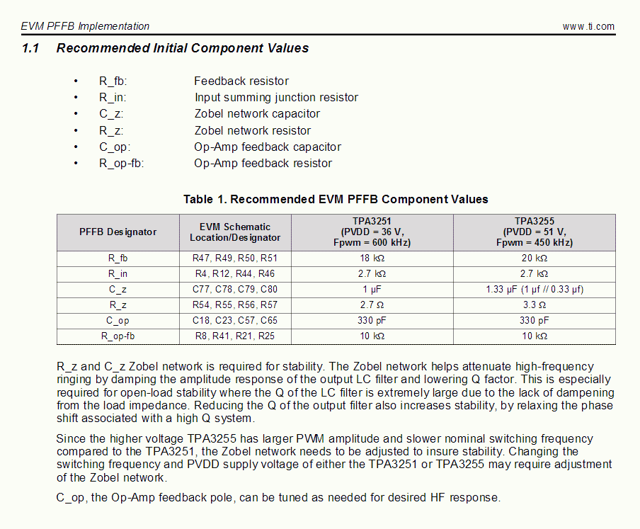
Values from PDF:
http://www.diyaudio.com/forums/attachment.php?attachmentid=692214&stc=1&d=1531763562
The EVMs PFFB is an older approach which (to my knowledge) wasn't stable with all loads. The newer implementation is stable at all time.
Voltwide implemented a minimal PFFB with only one capacitor per channel to tune for best square wave responce without overshoot even when unloaded.
The older SLAA702 isn't available from TI anymore, which was meant for the EVM, attached is a local copy.
Values from PDF:
http://www.diyaudio.com/forums/attachment.php?attachmentid=692214&stc=1&d=1531763562
Attachments
Last edited:
From my basic impressions all the pads needed are on the board, albeit you may need to come in with a daughterboard for the input coming off the accessory header (which I plan on doing regardless).
No, the 3251 and 3255 EVM where made for a different implementation, not having the capacitive "T" arrangement. They just use a single cap.
Hello
I bought the TPA3255evm board and am looking at this power supply
Mean Well HLG-320H-48B
There are a few attributes which I like about this series: Global AC Input for 220 and 110 as I'm traveling between US and India, no fans, no exposed parts, and wiring is simplified. However, before purchasing I would like to make sure I've not missed an attribute which would not work for the EVM board.
Thanks in advance,
Robert
sorry to ask nooby question
in the TPA3251 dataheet /chapter 7.5 its written a gain of 20dB.
i measured with differential probe on the outputs 23 Vpp. input is 400mVrms.
psu 31V.
so 0,4vrms = > Upp= 2,828 *Urms = 2,828 *0,4 = 1,1313 Vpp
formula:
gain = 20 * log (Vou/Vin)... 20*log(23/1,1313) ......i got 26,1 dB
what did i wrong???
Nope, the TI EVM's have a soldered-on tab that shorts out the output coupling capacitors (since in bridged configuration both speaker terminals are floating to the same DC value). This would be a VERY BAD THING in single ended, so you need to desolder the tabs to ensure the output is AC coupled.
I know nothing about the Nobsound parts. At $75 USD the TI EVM is very very hard to beat.
DPH, I'm curious if that statement is true for SE input & output, as TI ships the EVM in 2 channel, SE mode, with the soldered on shorting tabs present on the output caps. What is the result if used with the bridging tabs are left in place when using to drive 2 channels at 8 Ohms each? Basically, SE mode. Why would TI ship with default jumpers set to SE mode but with the bridging tabs requiring removal to use as SE? Rather odd choice by TI, but maybe I'm missing something. I want to use the EVM as SE input and SE output (driving 2, 8 Ohm speakers, one per channel).
Larzman, we need to differentiate between the input and output: the board as received is configured for single ended input and bridged output. There are 4 single ended outputs on the 3255, but most people are using the amp in the stock bridged set up, where the solder tabs should remain. Single ended outputs (eg running the system in 2+1 or 4 channel mode) requires the solder tabs removed.
.
.
Rather odd choice by TI, but maybe I'm missing something. I want to use the EVM as SE input and SE output (driving 2, 8 Ohm speakers, one per channel).
Writing more completely now that I'm not on my phone: if you're driving 2 channels in total from 1 3255 EVM board, you're running the system in bridged output. The solder tabs should remain in this configuration. If you want to drive 3 + speakers from the EVM board, then the tabs have to come off on the respective *non-bridged* outputs.
Hopefully this clears it up.
- Home
- Amplifiers
- Class D
- TI TPA3255EVM