Thanks, Washullu,
Looked at the CONNEX supplies. Seems they're less noisy than the MEANWELLs I looked at.
They all have two rails - can you wire them in series to get the single rail voltage needed? I see they offer a custom service but see nothing mentioned about whether that includes making single rail versions.
What did you do?
Found much of what they wrote to be interesting.
I am surprised to see all of those polar electrolytics used in these amplifier modules input stages: TI's and CONNEX's. CONNEX even cautions about being tempted to replace these with as they aptly called them "potato sized" capacitors. I might not have gone that far in size! Also found it interesting their cautioning about removing the input cap. My version would be driven by a cap coupled output stage of the crossover (with verified zero offset). I would be tempted to bypass the input caps. Of course, I will try it as it was delivered at first.
One thing for sure this approach is getting better quickly.
I am surprised to see all of those polar electrolytics used in these amplifier modules input stages: TI's and CONNEX's. CONNEX even cautions about being tempted to replace these with as they aptly called them "potato sized" capacitors. I might not have gone that far in size! Also found it interesting their cautioning about removing the input cap. My version would be driven by a cap coupled output stage of the crossover (with verified zero offset). I would be tempted to bypass the input caps. Of course, I will try it as it was delivered at first.
If you're talking about DC coupling the TI board, mind that it's a single supply layout and, well, the input will be sitting at half of the input buffer's Vpos. You want to AC couple.
Thanks, Washullu,
Looked at the CONNEX supplies. Seems they're less noisy than the MEANWELLs I looked at.
They all have two rails - can you wire them in series to get the single rail voltage needed? I see they offer a custom service but see nothing mentioned about whether that includes making single rail versions.
What did you do?
They have single rail supplies here and here and here (it is hard to tell which from which though on the website).
For faster shipping in the USA, you can find some Connex single rails here
Last edited:
If you're talking about DC coupling the TI board, mind that it's a single supply layout and, well, the input will be sitting at half of the input buffer's Vpos. You want to AC couple.
No, I was (and still am) talking about the coupling caps for the input signal not decoupling caps for the power supply.
When i get it running and settled in I will see what it thinks of no input couplers. Sure hate the idea of plain ol' electrolytics in that position ...
By AC coupling I mean having a capacitor on the input to block DC (versus DC coupling).
Unless your input is sitting on ground, you absolutely want to AC couple the input. Remember the EVM has a 0, +12 for the input opamps, and a +48-53 V depending on what your power supply is. This is not a split rail design.
Go look at any single supply opamp circuit, and you're going to see the input is AC coupled.
Edit to add: read this, as it's relevant to the what's going on http://www.ti.com/lit/an/sloa030a/sloa030a.pdf
Last edited:
DPH - you say that you must desolder the caps when using SE. Post 694, " the TI EVM's have a soldered-on tab that shorts out the output coupling capacitors" , I don't think that's true. I desoldered nothing on my 'EVM and its working without issue, driving 2, 8 Ohm Definitive Technology floor-standing speakers. Sounds very good, although I haven't yet connected up a music source that I like using my mobile phone as the controlling device for volume, song, etc.
The EVM I received last week is shipped set up for SE, and the discount code still works for those wondering about it. $75, free shipping from Texas.
The EVM I received last week is shipped set up for SE, and the discount code still works for those wondering about it. $75, free shipping from Texas.
DPH - you say that you must desolder the caps when using SE. Post 694, " the TI EVM's have a soldered-on tab that shorts out the output coupling capacitors" , I don't think that's true. I desoldered nothing on my 'EVM and its working without issue, driving 2, 8 Ohm Definitive Technology floor-standing speakers.
I want to be 100% abundantly clear here, as what you quote back to me is not what I attempted to convey, and don't want people to get the wrong idea entirely and damage their equipment. As a note, this is all clearly spelled out in the EVM manual. I fully appreciate that we're getting a lot of folk coming through with varying electronics experience, but want to remind y'all the EVM manual is excellent.
The photo is of the underside of the TPA3255 EVM board, with the output facing the left side.
On the OUTPUT SIDE, there are a series of jumpers (J22-J25) that short out the output coupling capacitors (the purple ones on next to the speaker terminals). The capacitors are not needed under bridged operation, but are absolutely necessary for single ended output. When running the OUTPUT in SINGLE ENDED (not bridged), these must be removed, as is clearly labeled in the photo. The input is configurable between differential and single ended via jumpers.
You are running the INPUT SINGLE ENDED, with a BRIDGED OUTPUT, as am I for the moment. (until my active xovers are done, whereupon I'll be running my mid/tweet off these boards in SE, with the woofer bridged)
Attachments
Maybe I misunderstand the appropriate terminology for what I need, drive a pair of 8 Ohm speakers (one amp channel to each speaker, basic stereo), about the simplest application for the 'EVM. I think this is stereo BTL operation, yes?
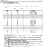
According to the TI manual for the TPA3255EVM, Table 3, J22, J23, J24, J25 are IN for stereo BTL operation, which is the default state of the EVM. Am I missing something?
According to the TI manual for the TPA3255EVM, Table 3, J22, J23, J24, J25 are IN for stereo BTL operation, which is the default state of the EVM. Am I missing something?
Attachments
one amp channel to each speaker, basic stereo
This is a four channel amplifier. When using the default output setting (BTL), you are using two amp channels per speaker.
Although I don't like the + and - speaker labels, think of it this way...
amp 1--->non-inverted left output--->left speaker +
amp 2--->inverted left output--->left speaker -
amp 3--->non-inverted right output--->right speaker +
amp 4--->inverted right output--->left speaker -
Because the voltages on the - side of the speaker is the inverted voltage of the + side, there is no need to pass the signal through a capacitor, so they can be bypassed. Because the output is high voltage, a heavier gauge soldered jumper is needed to handle the current.
Hope that helped.
Mike
The other way to think about it is each output terminal is sitting pretty much at the center point between the two power rails. In the case where you have +0 and +48V, like the TPA3255, the output nominally sits at +24 VDC. In a bridged amplifier, you're connecting between the "hot" side of 2 amplifiers, so both the inverting and noninverting side are sitting at +24 VDC, so there's no potential difference across the speaker (until a signal is actually applied). The speaker in a bridged amplifier is not ground referenced.
In single ended output, the speaker IS ground referenced, so there's +24 VDC on one side of the speaker and 0 VDC on the other side. Thus you NEED the coupling capacitor on the output to block that DC.
In single ended output, the speaker IS ground referenced, so there's +24 VDC on one side of the speaker and 0 VDC on the other side. Thus you NEED the coupling capacitor on the output to block that DC.
Dear tweakers,
I just finished a test setup with my new board tpa3251evm and I have a question I ask here because there is no dedicated thread for it (and question also relevant for tpa3255evm).
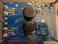
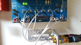
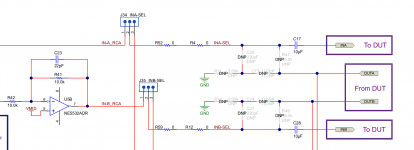
In order to have less components in signal path, I bypassed the input op amps, resistors and caps and connected audio signal (single ended) immediately before last couplings caps (C17,C28,C56,C63 same numbers on both boards). I pay the price of half power for this wiring, but I don't care with my 95db speakers. See picture : onboard jumpers allows this easy.
But the last caps before tpa chip are still there, and I think they are not audiophile grade. On my board they are 10µF ceramic (X7R, 1206) and on tpa3255 documentation I find them to be electrolytic (EEE-FK1C100R) or is this an error and also ceramic.
Anyway, I'm tempted to suppress also those onboard ceramic coupling caps and place only good film caps in the signal path between my diy dac output (Burson V6) and the tpa chip input pins.
Has anyone done this or is planning ? I think there can be some potential of improvement here. I remember when I found the right input coupling caps for my tripath ta2022 amp, sound quality improved nicely.
Dominique
I just finished a test setup with my new board tpa3251evm and I have a question I ask here because there is no dedicated thread for it (and question also relevant for tpa3255evm).
In order to have less components in signal path, I bypassed the input op amps, resistors and caps and connected audio signal (single ended) immediately before last couplings caps (C17,C28,C56,C63 same numbers on both boards). I pay the price of half power for this wiring, but I don't care with my 95db speakers. See picture : onboard jumpers allows this easy.
But the last caps before tpa chip are still there, and I think they are not audiophile grade. On my board they are 10µF ceramic (X7R, 1206) and on tpa3255 documentation I find them to be electrolytic (EEE-FK1C100R) or is this an error and also ceramic.
Anyway, I'm tempted to suppress also those onboard ceramic coupling caps and place only good film caps in the signal path between my diy dac output (Burson V6) and the tpa chip input pins.
Has anyone done this or is planning ? I think there can be some potential of improvement here. I remember when I found the right input coupling caps for my tripath ta2022 amp, sound quality improved nicely.
Dominique
Attachments
Last edited:
I guess you should post the question to the TI engineers who designed the board on why all those components are there if they are not really needed. This board is not one of those one can pick up at EBAY "designed" by unknown people using components of questionable quality.
My point is, the purpose of modding is to "improve" things. But before that, one should try to understand how the board operates before changing things. Anyway, , this is your board, you are free to do what ever you like.
Regards,
My point is, the purpose of modding is to "improve" things. But before that, one should try to understand how the board operates before changing things. Anyway, , this is your board, you are free to do what ever you like.
Regards,
Dear tweakers,
I just finished a test setup with my new board tpa3251evm and I have a question I ask here because there is no dedicated thread for it (and question also relevant for tpa3255evm).
In order to have less components in signal path, I bypassed the input op amps, resistors and caps and connected audio signal (single ended) immediately before last couplings caps (C17,C28,C56,C63 same numbers on both boards). I pay the price of half power for this wiring, but I don't care with my 95db speakers. See picture : onboard jumpers allows this easy.
But the last caps before tpa chip are still there, and I think they are not audiophile grade. On my board they are 10µF ceramic (X7R, 1206) and on tpa3255 documentation I find them to be electrolytic (EEE-FK1C100R) or is this an error and also ceramic.
Anyway, I'm tempted to suppress also those onboard ceramic coupling caps and place only good film caps in the signal path between my diy dac output (Burson V6) and the tpa chip input pins.
Has anyone done this or is planning ? I think there can be some potential of improvement here. I remember when I found the right input coupling caps for my tripath ta2022 amp, sound quality improved nicely.
Dominique
I don't know of any thread more dedicated to this board than this one!
I, too, wish there was more spirit for tinkering with this board but I also know that many of these people have been playing with this stuff for far longer than I (this is my first class D project) and they know more about what works and what doesn't.
When I first looked at the schematic I, too, wished there wasn't a 5532 being run on just 12 volts - not even a negative rail! - and all of those polarized electrolytic capacitors. It just cannot be right!
I am waiting for a power supply, a CONNEX as recommended to me by wushullu, so I have not had a chance to hear the thing. My application will be limited to about two octaves , 40 hz to just over 160 hz, so I will not be too hard to please. Hoping this will replace my CREST ProLite amps which do sound better than I would have expected but their gain of 75 is just too much within my system. The gain of approx 20 of the 3255EVM is just right for my setup.
I am fascinated by your bypassing the input stage. You cannot remove the cap before the 3255. You can replace it, of course. I am thinking, as long as you have verified no dc offset leaving your preamp you have to be able to get away without the input cap but it is made clear that there must be a cap before the 3255.
The fellow who makes the CONNEX supplies makes a point within their website that the large caps we would tend to want to substitute for the polarized electrolytics could well sound WORSE. I think the size is very important here as it affects the length of the signal path.
Wish there were BLACK GATE Ns still available.
I look forward to hearing what you think of the sound with your mod.
If I may ask what, other than our attempts to compare to actual music being performed, amplifier will you be most familiar with in your comparison?
Having no input stage I would worry you might run into noise problems but nothing beats actually TRYING something and for that you have my respect. Too many of us want to be in a debating society instead of at a kitchen table laboratory with a soldering iron followed by some listening to what we have done.
An audio system is the most satisfying puzzle ever devised. It is never solved but always remains interesting.
MBoxler and DPH, thanks for both of your responses, although they seem to conflict with each other. If the unit is shipped with the solder bridges, which I think it is (I'll verify when I get home and can see it), I'm wondering why TI ships them with the solder bridges yet all other jumper defaults are for BTL (2 channel) operation. If DC was present on the outputs, I think my speakers would be toast by now, which they are working fine.
In order to have less components in signal path, I bypassed the input op amps, resistors and caps and connected audio signal (single ended) immediately before last couplings caps (C17,C28,C56,C63 same numbers on both boards). I pay the price of half power for this wiring, but I don't care with my 95db speakers. See picture : onboard jumpers allows this easy.
They're also 1206 ceramic capacitors on the TPA3255 board, so this is in error. That said, I don't know if they're 10 uF X7R's just by looking at them (though my suspicion is you're right on the X7R if not the value), and they sit between the output of the NE5532 and the input of the 3255, so this should be a pretty high impedance load across the cap. Don't know what you'll be able to fit on the 1206 pads though.
Thank you rickmcinnis for what you wrote.
Currently this Ti TPA3251EVM board fed like shown above sounds already very very good, better than all my other amps and is also dead silent to my ears (without signal). Very easy listening. Ultra detailed. I choose this board and not a cheaper Chinese one for it's potential of tweaking (PFFB predisposition, connectors, space, etc) and ultra good build quality and documentation quality.
Power supply is Meanwell LRS-350-36. I needed to add a lot of bulk caps to have nice bass. Otherwise sound was to thin and not dynamic. I hesitate to give more details on this because someone will say Ti calculator spreadsheet for bulk caps gives 400µF where I had to place 25x more to mach the basses of my smaller tripath Ta2022 amp (with same amount of bulk caps).
Not sure indeed a big film cap on input coupling will bring something more due to its size. On the other side I heard big difference by placing film caps on input of one tripath amp and on a small Chinese tube amp. So it's worth to try. Goal is to find the audiophile quality of the tpa3251 itself.
As far as I have understood the input stage, one function helps feeding in a correct way the tpa chip which has differential input with a single ended signal. Therefore the need of op amps. If I can avoid, I avoid. And this is what I did. I did not mention that I increased also the supply tension of the chip AK4495 from 5V to 7V inside my DAC. This compensates partly the loss of signal level due to missing negative part of differential audio signal. I think later I will modify my DAC to have differential outputs. I just need some additional components and 2 other Burson discrete op amps. Then I can feed the tpa inputs in the normal differential way and certainly profit from more noise cancelling.
My amplifiers : TA2022 chinese heavily tweaked, small tube amp EL84/12ax7 with some changes, heavy Onkyo AV the worst of all ( will end in basement or garage if wife accepts).
My diy DAC (is a streamer in fact) : >10 kg, 7 power supplies (2xReflektor D, 4xStuder900, 2 times 300VA for DAC and output stage, tweaked dac module ak4495, own design output stage with 2 Burson V6, Pi 2, Kali, PieCorePlayer and LMS on debian server, Qobuz Hi-res account.
- Home
- Amplifiers
- Class D
- TI TPA3255EVM