I'm afraid I do not have much more information, my two 200ac modules quit about a year ago with a short shrieking noise and after that nothing. The 200asc refused to produce any sound after I took the pictures although the led indicates that it is OK.
I have no idea on what to measure or even what went wrong.
I have no idea on what to measure or even what went wrong.
Damn, these modules are brittle, and it does not include a MCU system to give a hint for quick repair startup. Some generic test recommendations for SMPS/class D modules, in order:
- Check for mistakes in input wiring, I think I saw traces of wires being directly soldered to PCB connector pins one by one.
- Check standby supply (with module disabled).
- Check that signal supply rails and main power rail come on correctly upon module activation.
- Check that output stage is oscillating (carrier present at output). Check output offset. Check idle frequency.
- Check responsiveness to input signal. Follow signal through op-amp/IC chain if needed.
Hello gentlemen!
I bought a PS Audio Trio A-100-US power amplifier from the United States on iceasc 200asc modules. PS audio has buried something in the power of icepower boards and I have to use a transformer from 120 to 230V. Do you know what I need to change at the power input of ICEpower modules to power them directly from 230V? Please, help me if You can")
Regards!
I bought a PS Audio Trio A-100-US power amplifier from the United States on iceasc 200asc modules. PS audio has buried something in the power of icepower boards and I have to use a transformer from 120 to 230V. Do you know what I need to change at the power input of ICEpower modules to power them directly from 230V? Please, help me if You can
Regards!
Hello gentlemen!
I bought a PS Audio Trio A-100-US power amplifier from the United States on iceasc 200asc modules. PS audio has buried something in the power of icepower boards and I have to use a transformer from 120 to 230V. Do you know what I need to change at the power input of ICEpower modules to power them directly from 230V?
Regards!
Hello gentlemen!
PS audio has buried something in the power of icepower boards and I have to use a transformer from 120 to 230V. Do you know what I need to change at the power input of ICEpower modules to power them directly from 230V?
Regards!
Really? The 200 asc is normally Universal Mains SMPS (85 VAC to 265VAC , 47Hz - 63Hz) That"s what the specs say...
Yes, I know, but PS Audio is something modifying and doing things for 120V for USA and Japan, and 230V for Europe When I connected 230V, I heard high-frequency squeak and turned off the differential switch at home. Fortunately, after connecting back under 230 / 120V amplifier worked ...
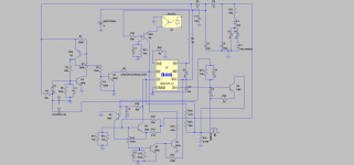
When I connected 230V, I heard high-frequency squeak and turned off the differential switch at home. Fortunately, after connecting back under 230 / 120V amplifier worked ...Ok time to bring this up a notch as I've finally managed to make a schematic of the circuit surrounding the NCP1203 in the power supply. B&O certainly didn't keep it simple!
The capacitor values are obviously unknown. If necessary I can pull them from the circuit and measure them. Obviously really small values are a pain to measure.
In removing the sense resistors for the schematic C3 crumbled away, which in hindsight is probably a good thing, otherwise I wouldn't have known it was busted. Either way I have no idea what value it should take.
D1 is most likely a zener, it was dead on arrival and I've no idea what value it should be. Other things were also broken, but as far as I can tell, I've replaced them successfully. Hopefully all the replaced, small signal, BJTs are the correct polarity.
The circuit doesn't start up. I've had it started by powering the NCP separately and I've had it regulating correctly too. But alone, it wont start.
So anyone any ideas?!
As far as I can see I should be able to disconnect a decent amount of the supplementary circuitry around the NCP1203 without affecting its ability to actually regulate the primary supply and current limit. I have tried the circuit without R2 in place and this makes no difference. This kind of leads to me to believe that even if I replaced D1 it wouldn't make any difference as, as far as I can see, the point of the circuitry around D1 is to drive FB low under a fault condition.
Attachments
@ 5th element
Post 13. That via may not actually go right through the board. I have a Ver K open at the moment whick looks much like the unit you don't have If I measure between the transistor pin you indicate and pin 2 on the IC, I get 10 ohms. But there is no resistor in series that I can see.
Further, the via is inline with another via more or less centred between 2 pins on the transformer, so a nice reference to look for when flipping the board. The via you want traced in nowhere to be seen. Either it comes up under the controller IC, or it is a blind via and goes into the internal layer. If you shine a torch from behind you can see this board has at least 3 layers, maybe more.
Your crumbed capacitor you make reference to, is that the large smd ceramic between the mosfet and the transformer?
Post 13. That via may not actually go right through the board. I have a Ver K open at the moment whick looks much like the unit you don't have
If I measure between the transistor pin you indicate and pin 2 on the IC, I get 10 ohms. But there is no resistor in series that I can see.Further, the via is inline with another via more or less centred between 2 pins on the transformer, so a nice reference to look for when flipping the board. The via you want traced in nowhere to be seen. Either it comes up under the controller IC, or it is a blind via and goes into the internal layer. If you shine a torch from behind you can see this board has at least 3 layers, maybe more.
Your crumbed capacitor you make reference to, is that the large smd ceramic between the mosfet and the transformer?
Yeah I have had the IC off and investigated there are vias that come up under it.
In my case the crumbled capacitor is a small one that sits next to the three current sense resistors next to the main MOSFET switch.
The large 100nf is fine in my case.
I haven't actually done anything with the module for a long time.
In my case the crumbled capacitor is a small one that sits next to the three current sense resistors next to the main MOSFET switch.
The large 100nf is fine in my case.
I haven't actually done anything with the module for a long time.
Yeah I have had the IC off and investigated there are vias that come up under it.
In my case the crumbled capacitor is a small one that sits next to the three current sense resistors next to the main MOSFET switch.
The large 100nf is fine in my case.
I haven't actually done anything with the module for a long time.
I have drawn out my ver. K (just the primary as you have) which is in some ways quite different to yours but maybe will give you a new perspective. Component values (where obtainable) are correct as this is a working board. It's in PDF format. Problem is I can't log in with my computer as I don't remember my password. I emailed the PDF to myself on my iPad but there is no way to upload it from here. In the past, requests for lost passwords have always failed and I end up creating a new identity which for some reason does work. But now I have 3 (none of which I know the password for) and don't want yet another one. I could always email it to you direct. Will try and find a way to recover password in the interim.
Benefits of hoarding email - seems there was once a successful reset and the PW is still good
Hopefully there are no stupid mistakes. If anyone spots anything off, please let me know and I'll amend it. Who knows, if everyone chips in a section, one day we may even have a complete schematic
Hopefully there are no stupid mistakes. If anyone spots anything off, please let me know and I'll amend it. Who knows, if everyone chips in a section, one day we may even have a complete schematic
Attachments
Hello all,
I had a rather odd thing happen a while back with an ICEPower module - it was not a 200ASC but the 50ASX2...the module would not wake up unless connected mains were under 100v. At 120V (in my case mains are measured around 127vac) it would not work. Only when I put the module on my variac and lowered mains would it awake...weird....
I had a rather odd thing happen a while back with an ICEPower module - it was not a 200ASC but the 50ASX2...the module would not wake up unless connected mains were under 100v. At 120V (in my case mains are measured around 127vac) it would not work. Only when I put the module on my variac and lowered mains would it awake...weird....
..err, slight error on the previous pdf. IC CS (current sense) circuit connected direct to ground instead of the Source sense resistors, then to ground. Ditto for C49. Sorry about that. Could a moderator delete the previous pdf file please?
Attachments
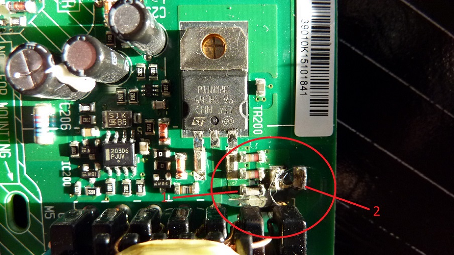
You have to be careful with that one, the large cap# 2 is a 0.1uF rated at something like 1000V.
I think the three resistors are each 0.47R but that's just off the top of my head.
Why you need to be careful here is because if the current sense resistors are broken then the main MOSFET is probably blown too and along with it possibly more. You need to measure the FET with a continuity tester (the setting that beeps) between the soldered tab and the leg next to #1. It should measure high in resistance, if it beeps then the FET is dead too.
Are the resistors actually dead? They don't look charred.
Thank you very much for response!You have to be careful with that one, the large cap# 2 is a 0.1uF rated at something like 1000V.
I think the three resistors are each 0.47R but that's just off the top of my head.
Why you need to be careful here is because if the current sense resistors are broken then the main MOSFET is probably blown too and along with it possibly more. You need to measure the FET with a continuity tester (the setting that beeps) between the soldered tab and the leg next to #1. It should measure high in resistance, if it beeps then the FET is dead too.
Are the resistors actually dead? They don't look charred.
I measured all three resistors (number 1) with continuity tester and it seems they are ok. The large cap# 2 doesn't pass continuity test.
The second one could be replaced with 1000PF 1KV ceramic cap, i found this info on another site, is it correct?
The #2 cap is a basic decoupling cap but for high voltage. It's a 0.1uF or 100nF.
The #2 cap should measure as pretty much infinite ohms when it's resistance is measured. If it's measuring as a short circuit, zero ohms, then it's dead. Can you measure capacitance with your multimeter?
A 630 or 1kV part should do as a replacement.
The #2 cap should measure as pretty much infinite ohms when it's resistance is measured. If it's measuring as a short circuit, zero ohms, then it's dead. Can you measure capacitance with your multimeter?
A 630 or 1kV part should do as a replacement.
Just an update - replaced cap with new one for 2kv DEBB33D222KA2B and it works fine now. Thanks for help!The #2 cap is a basic decoupling cap but for high voltage. It's a 0.1uF or 100nF.
The #2 cap should measure as pretty much infinite ohms when it's resistance is measured. If it's measuring as a short circuit, zero ohms, then it's dead. Can you measure capacitance with your multimeter?
A 630 or 1kV part should do as a replacement.
- Home
- Amplifiers
- Class D
- B&O Icepower 200ASC pictures