...amp arrived...
Hi
here some "first look"
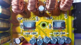
delivery over 3 days/amazon- cost 33Euro - grey/titan look, very good packed, 3 bubble foils very good craft man ship.very small, pcb and solders good quality.
at the power plug they forgot to solder the 2 gnd pads
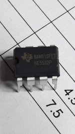
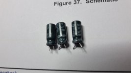
i am not sure if the 10x 470µF/35V are "real" or fake
power consumption:24V/no signal
amp switched off - 30mA--> 0,72Watt
amp switched on - 60mA-->1,44Watt
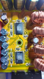
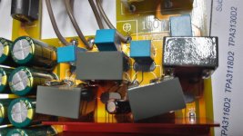
tabel 1 - attachment show the coils and caps measured at 100khz with my lcr meter.
coils about 20µH, caps about 680-713nF/voltage on the grey surface shows 63V...ESr @100khz is about 0,13R...
my blue foil TDK 0,68/100V show--> 710nF/ ESR 0,08R
chris
Hi
here some "first look"
delivery over 3 days/amazon- cost 33Euro - grey/titan look, very good packed, 3 bubble foils
very good craft man ship.very small, pcb and solders good quality.at the power plug they forgot to solder the 2 gnd pads
i am not sure if the 10x 470µF/35V are "real" or fake
power consumption:24V/no signal
amp switched off - 30mA--> 0,72Watt
amp switched on - 60mA-->1,44Watt
tabel 1 - attachment show the coils and caps measured at 100khz with my lcr meter.
coils about 20µH, caps about 680-713nF/voltage on the grey surface shows 63V...ESr @100khz is about 0,13R...
my blue foil TDK 0,68/100V show--> 710nF/ ESR 0,08R
chris
Attachments
-
TPA3116D_dual chip_readyamp_coils and caps.pdf393 KB · Views: 131
-
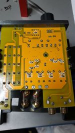 TPA3116 dualchip inside_button.jpg357.9 KB · Views: 740
 -
 TPA3116 dualchip inside_top pcb without heatsink.jpg414.9 KB · Views: 735
 -
 TPA3116 dualchip inside_caps coils.jpg370.4 KB · Views: 740
 -
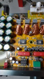
 TPA3116 dualchip inside_gain configuration.jpg381.2 KB · Views: 704
chips are on PBTL mode
Hi
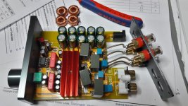
just checked ...red circle on both chips= PBTL config. ok
what is not correct is the gain configuration. 100k and 473R marked on both sides it shoud be 100k and 39k for 32db gain at the TPA chip
what i not found is which chip is master /slave? the pin16 sync i see no connection. datasheet recommend pin 16master 10k to slave pin16 and 1nF to GND
chris
Hi
just checked ...red circle on both chips= PBTL config. ok
what is not correct is the gain configuration. 100k and 473R marked on both sides it shoud be 100k and 39k for 32db gain at the TPA chip
what i not found is which chip is master /slave? the pin16 sync i see no connection. datasheet recommend pin 16master 10k to slave pin16 and 1nF to GND
chris
Attachments
Last edited:
24V psu 8R and 4R load test
Hi
here some pics after 26 hours run in with a 0,1V sweep signal (10Hz-35khZ)
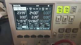
load test is with 8R and 4R load at my rigol psu at 24V.
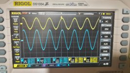
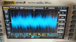
1khz
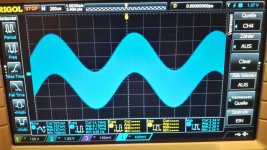
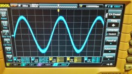
pic 150mV input / 8Rand max volume no clipping possible...23 Watt
pic 2 300mV input / 8R slightly under clipping 28 Watt
pic 3 300mV input /4R slightly under clipping 51 Watt
pic 4 rigol 832A @ 4R is limited at 6A
really a clean signal..if i zoom in at the scope i cant see the frequency what the 3116 is using..
chris
Hi
here some pics after 26 hours run in with a 0,1V sweep signal (10Hz-35khZ)
load test is with 8R and 4R load at my rigol psu at 24V.
1khz
pic 150mV input / 8Rand max volume no clipping possible...23 Watt
pic 2 300mV input / 8R slightly under clipping 28 Watt
pic 3 300mV input /4R slightly under clipping 51 Watt
pic 4 rigol 832A @ 4R is limited at 6A
really a clean signal..if i zoom in at the scope i cant see the frequency what the 3116 is using..
chris
Attachments
really a clean signal..if i zoom in at the scope i cant see the frequency what the 3116 is using..
The TPA3116 does not use one frequency, the chip shifts the oscillating frequency strategically.
datasheet said:The TPA31xx advanced oscillator/PLL circuit employs a multiple switching frequency
The TPA3116 does not use one frequency, the chip shifts the oscillating frequency strategically.
hi ICG
i thought that the frequency is set by the AM0, AM1, AM2 pins (pin13,14,15), not?
first listening test...
Hi
after "burn in" of 48 hours i start a listening test yesterday.
to make long short- this amp is smaller then the FX502spro and it really sounds good. voices and instruments are natural and the gain is not as "dramatig" then i thought.
nevertheless not as good as my modded FX502Spro /tpa3250) but reall nice.
What do i miss?
for my experience the 2 ends of the listening spectrum. bass too blubby and the details and a kind nasty top end spectrum.
soundstage is "flat" in deepness and more separation of the singers would be nice...
modding is started...the plaace inside is horribel
you will see..
chris
first moddification
Hi
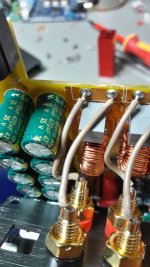
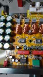
here is my mod.
i measrued the gray caps after 48hours "burn in2 and it gets a worse ESR at 100khz-->0,15...0,17...so they go out!
the 10µH is reall not my best choise becasue i learnt from moding the fx502spro that this are "collored" k2 output coils....but i have nothing others in my hand...
the room inside is really not much
listening test at the weekend
small coil proposal are very welcome
chris
Hi
here is my mod.
i measrued the gray caps after 48hours "burn in2 and it gets a worse ESR at 100khz-->0,15...0,17...so they go out!
the 10µH is reall not my best choise becasue i learnt from moding the fx502spro that this are "collored" k2 output coils....but i have nothing others in my hand...
the room inside is really not much
listening test at the weekend
small coil proposal are very welcome
chris
Attachments
Last edited:
first try fail.....???...listening test...fake opamp...
Hi
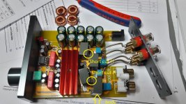
after the change of the output filter and 1 day "burn in" i want to try it to listening. first i get no signal on the right channel?? what happened??
if you look at the pic you will see the yellow circles. Watch out that you dont get shorten the coils during close the amp housing.
after butting an isolation in between everything is was working fine...
the listening test was strange...the general setup is better but i dont understand why the amp was still harsh and nervous, especially at female voices and high hats???? i follow the setup for PBTL and i use for 8R speakers this würth soft poly ferrit.... i change to 10µ/0,68....
then i remember that i had a Fake op amp at the YJ TPA3255 board. so i pull out this "version" of Ne5532 and but an LM4562 in.......yep this was the reason..now the sound is fine.. the compare test with my mod TPA3250 -FX502spro is now fair...
i am still thinking which coil 10µ will fit here...the original space is about 16mm diameter...
...continue...
chris
Hi
after the change of the output filter and 1 day "burn in" i want to try it to listening. first i get no signal on the right channel??
what happened??if you look at the pic you will see the yellow circles. Watch out that you dont get shorten the coils during close the amp housing.
after butting an isolation in between everything is was working fine...
the listening test was strange...the general setup is better but i dont understand why the amp was still harsh and nervous, especially at female voices and high hats????
i follow the setup for PBTL and i use for 8R speakers this würth soft poly ferrit.... i change to 10µ/0,68....then i remember that i had a Fake op amp at the YJ TPA3255 board. so i pull out this "version" of Ne5532 and but an LM4562 in....
...yep this was the reason..now the sound is fine.. the compare test with my mod TPA3250 -FX502spro is now fair...i am still thinking which coil 10µ will fit here...the original space is about 16mm diameter...
...continue...
chris
Attachments
sound check 2...
Hi
i really propose to set the gain down!
as i had done a listening session vs. fx502Spro the sound is fine but the arrangement is still too strong in the middle of the loudspeaker--> this smear the other voices and instruments in the corner.
now i am ready with setting the gain to 100k/20K =26dB instead of 32dB
its sounds more "together" the hole arrangement is more close and in the same rhythm and timing..
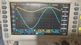
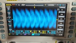
pic 1 noise at Rchannel- input shorted
pic 2 noise at the Lchannel- input shorted
why are these measurements so different??
chris
Hi
i really propose to set the gain down!
as i had done a listening session vs. fx502Spro the sound is fine but the arrangement is still too strong in the middle of the loudspeaker--> this smear the other voices and instruments in the corner.
now i am ready with setting the gain to 100k/20K =26dB instead of 32dB
its sounds more "together" the hole arrangement is more close and in the same rhythm and timing..
pic 1 noise at Rchannel- input shorted
pic 2 noise at the Lchannel- input shorted
why are these measurements so different??
chris
Attachments
change input caps....
Hi
if you wan to change the 2,2µF/50V bipolar input caps for both TPA chips please look at the pic....yellow marked circle. 2 caps for the left chip and 2 caps for the right chip.
question:
the blue circle are the caps for the plimit-GVDD and GND. they are original bipolar caps 2,2µF/50V
at the datasheet its written:
Internally generated gate voltage supply. Not to be used as a supply or connected to any component other than a 1 μF X7R ceramic decoupling capacitor and the PLIMIT and GAIN/SLV resistor dividers.
so electrolytic is nonsense here?
chris
Attachments
Last edited:
hi ICG
i thought that the frequency is set by the AM0, AM1, AM2 pins (pin13,14,15), not?
That's the base oscillation frequency. The modulation actually diverts from that frequency, the IC decides what frequency/modulation is actually used.
pic 1 noise at Rchannel- input shorted
pic 2 noise at the Lchannel- input shorted
why are these measurements so different??
That's because the modulation and its frequency is chosen upon the signal and power/frequency spread and does, in fact, change to provide the highest efficiency and to distribute the losses. That's the effect of the changed modulation. You can still see it cycles at the same time (around ~1,15 periods) because of the takt frequency. The IC probably 'decides' upon the actual load and voltage drop. It should be more uniform if you connect a constant impedance (i.e. 8 or 4 Ohm resistor) and/or use it in PBTL or slave mode. What impedance did you connect to the output?
That's the base oscillation frequency. The modulation actually diverts from that frequency, the IC decides what frequency/modulation is actually used.
That's because the modulation and its frequency is chosen upon the signal and power/frequency spread and does, in fact, change to provide the highest efficiency and to distribute the losses. That's the effect of the changed modulation. You can still see it cycles at the same time (around ~1,15 periods) because of the takt frequency. The IC probably 'decides' upon the actual load and voltage drop. It should be more uniform if you connect a constant impedance (i.e. 8 or 4 Ohm resistor) and/or use it in PBTL or slave mode. What impedance did you connect to the output?
thanks icg for that "complete" information. i am not finished to study the datasheet of the TPA3116. so i dont realize that the chip "choose" its frequency.
i made a miss measurement because it was without load
...actually its a mess on my workbenchre -measurment will be done...
chris
Today I got the breeze audio , as @horst303 said It's completely silent
I am still examing the amplifier so far I am satisified
looks like a good amplifier , here is a video of it that I uploaded today to youtube
YouTube
Hi there, can you tell me what size the power supply plug is for this amp? Is it 5.5mm x 2.1mm?
Hi there, can you tell me what size the power supply plug is for this amp? Is it 5.5mm x 2.1mm?
yes i can confirm this dimensions
(5,5mm x 2,2 is my plug)chris
Hi
if you wan to change the 2,2µF/50V bipolar input caps for both TPA chips please look at the pic....yellow marked circle. 2 caps for the left chip and 2 caps for the right chip.
chris
Hi
just to complete my findings...
here is a pic from this caps...what company is that...what about the quality...i dont know this label
thx chris
Attachments
...confused...
Hi
the last 2 evenings...
i am a little bit confused after my comparison tpa3116 with fx502spro.
after some listening session i want to setup the exact amp volume to compare as fair as possible. at listening i was happy with my setting of the volume knobs...
but..
after the measurements i am really confused.Why ?
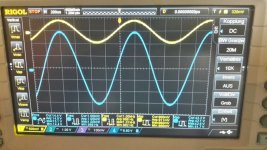
i put the differential probe at the terminal of the left channel and send via foobar a 1khz tone and i get different output levels??? the difference is too much i would say.........why?
i really did 5x re checking all the setup and i compare the volume by listening and its the "same" volume.
load is a 8R speaker, power supply is 24V ..
and
if i setup the tpa3116 at that level as i had at the other amp--> its f... loud at the listening session...so my ears are working..
pic 1 tpa3250 in fx502spro
pic 2 TPA3116 dual chip
HELP!!
chris
Hi
the last 2 evenings...
i am a little bit confused after my comparison tpa3116 with fx502spro.
after some listening session i want to setup the exact amp volume to compare as fair as possible. at listening i was happy with my setting of the volume knobs...
but..
after the measurements i am really confused.
Why ?i put the differential probe at the terminal of the left channel and send via foobar a 1khz tone and i get different output levels???
the difference is too much i would say.........why?i really did 5x re checking all the setup and i compare the volume by listening and its the "same" volume.
load is a 8R speaker, power supply is 24V ..
and
if i setup the tpa3116 at that level as i had at the other amp--> its f... loud at the listening session...so my ears are working..
pic 1 tpa3250 in fx502spro
pic 2 TPA3116 dual chip
HELP!!
chris
Attachments
Last edited:
The thick sine wave isn't just one signal. Increase the x-resolution (frequency), you'll see there a much higher frequency signal over the base sine wave. If you ignore that and just take the upper halve wave and just the top of the fat 'line', it's 2,4 units in height for the fx502spro and the 3116 is only a tad higher at 3 full units (0,1 units below the other amp). That means, the actual signal is pretty close, the huge difference is the modulated signal on top of the fx502spro output.
That means,
a. the loudness of the signal is already pretty close, you don't hear the 2nd frequency because it's too high.
and
b. if you didn't get a high frequency interference into the measurement system or connected it wrong (i.e. different gnd connection instead of the the amp - output, the TPA3250 is in a PBTL configuration too, after all), your fx502spro isn't developed cleanly and 'saved' on the output filters. Or in other words, it's crap.
Hi ICG
i really thank you and i appreciate your help for this small amp.
so every thing is fine.
1. can i setup the scope to get out this oscz frequ? i have to use the external trigger frequency input on the scope with my freq. generator.
2. at the chapter b you make it not really clear for me....sorry
chris
...better and smaller coils for output..
Hi
datsheet = overcurrent trip point is 7,5A - so pbtl is about 15A, right?
as i wrote in post 28 i want to search for better 10µH coils. i want to try this:
low cost and good current / inductance if you look at the datasheet
%product-title% kaufen
bourns srp-1250-100
what do you thing??
chris
Hi
datsheet = overcurrent trip point is 7,5A - so pbtl is about 15A, right?
as i wrote in post 28 i want to search for better 10µH coils. i want to try this:
low cost and good current / inductance if you look at the datasheet
%product-title% kaufen
bourns srp-1250-100
what do you thing??
chris
Last edited:
- Status
- This old topic is closed. If you want to reopen this topic, contact a moderator using the "Report Post" button.
- Home
- Amplifiers
- Class D
- New Breeeze Audio TPA3116 2.0 100W dual chip