Okay, 2 first. For a bridge tied amplifier the enclosure or power supply is not equal or neutral to the negative output. It may not be connected otherwise the chances are high you fry your amp. It is possible you connected the wiring of the ground/negative connector of the scope to the power supply instead of the amp output. It is also possible your scope did the (wrong) ground connection if it's connected to the power supply gnd or by your trigger, if it's connected to the amp input or your signal generator gnd. Another faulty wiring is on multichannel scopes if you leave one channel connected to one amp and use a different input for the measurement. There is the wrong ground connection happening over your scope ground. That's actually a very common mistake even electronics education teachers often overlook. Simple solution: Just use one channel at a time and disconnect the other connection or make the measurement with 2 different oscilloscopes.
You don't need an external trigger, the amp output is fine for auto trigger as long as it is periodically (i.e. sine, square, triangle or mixed signal of a fixed frequency). To see the high frequency part of the signal (or noise, might also be possible) switch the x-axis to a higher frequency/shorter period. You can let the scope do the calculating or count the units/dividers yourself and use a calculator. You don't need the exact frequency though, you have just to find where it's comming from. The manual of your scope will explain how to do that or you could search for an oscilloscope teaching video on YT or other sources.
You don't need an external trigger, the amp output is fine for auto trigger as long as it is periodically (i.e. sine, square, triangle or mixed signal of a fixed frequency). To see the high frequency part of the signal (or noise, might also be possible) switch the x-axis to a higher frequency/shorter period. You can let the scope do the calculating or count the units/dividers yourself and use a calculator. You don't need the exact frequency though, you have just to find where it's comming from. The manual of your scope will explain how to do that or you could search for an oscilloscope teaching video on YT or other sources.
Hi
2
i generally use the differential probe if i measure at playing/listening amp.
then i check all the supplies and connector if they are GND or not.
in my lab the power supply and the frequency generator is earth GND so i can use 2 probes.
first probe is the normal probe-channel 1 yellow - gnd to audio input /rca of the amp the hot at the signal
differential probe at the output of the amp
1
i know that if i change the time per division to its minimum i can see the working frequency- what i want is to "filter" out the 400khz to see the "hüllkurve"- envelope = the audio signal
thanks again
chris
first probe is the normal probe-channel 1 yellow - gnd to audio input /rca of the amp the hot at the signal
differential probe at the output of the amp
That's exactly what's wrong. You need both differential probes to be connected to the amp output + and - since the negative amp output is NOT the same as input GND! Do not connect it to the input RCA AT ALL! Just to use a differential probe does not make every and any potential independent if you connect it wrong!
i know that if i change the time per division to its minimum i can see the working frequency- what i want is to "filter" out the 400khz to see the "hüllkurve"- envelope = the audio signal
The signal you are getting is either because of the wrong measurement wiring, like already explained, or it's the bad implementation of the output filter. If you want just to compare the audible range voltage and it's not a measuring wiring fault, and don't want to read the visual curve on the display either, then you have use an output filter on the amp to get the correct response. Like it should have been implemented on the board in the first place.
Sorry i had yesterday birthday party of my son (11)...so i had no time to respond to this.
you wrote....
That's exactly what's wrong. You need both differential probes to be connected to the amp output + and - since the negative amp output is NOT the same as input GND! Do not connect it to the input RCA AT ALL! Just to use a differential probe does not make every and any potential independent if you connect it wrong
i do not write that i use the differential probe with 1 probe to input and 1 probe to the output. i use the diff probe generally on the outputs of the amp.
my description was not really clear...i see now...
in the lab my frequ. generator is earth gnd, the scope too. i use channel 1 (normal probe) to measure the input signal. the gnd clip of this probe i put on the input rca on shield. the probe i fixed on the e.g. left channel input rca.
this is wrong?????-
on the outputs i use the diff probe
chris
Where from does your differential probe get its power? If that power source is in any way connected to the same gnd or positive as the input or the amp power supply or the scope, then yes, that's wrong. If it isn't, it's simply a crap amp.
The diff probe get its power from a seperate power wall transformer.
and yes the crap singal at the fx502spro is strange --< i have to measure again and/or re check
thanks ICG
Hi
datsheet = overcurrent trip point is 7,5A - so pbtl is about 15A, right?
as i wrote in post 28 i want to search for better 10µH coils. i want to try this:
low cost and good current / inductance if you look at the datasheet
%product-title% kaufen
bourns srp-1250-100
what do you thing??
chris
pump it up....
Hi
datsheet = overcurrent trip point is 7,5A - so pbtl is about 15A, right?
On the New Breeeze Audio TPA3116 amp? There are two of them, the limit is each 7,5A, so the maximum current is 15A. However, you will not be able to use the amp full power since the heatsink is way too small for the power (should be ~6-8x the size for 200W or ~4x the size with a fan), there is no ventilation/air exchange and the connector got a too high contact resistance/too small contact surface for 15A, even 7,5A will cause it to heat up and to let the voltage drop. And you can't parallel bridge wire the two channels, unless you modify the board to let both amp ICs sync. If you do that, you'll only get the maximum power on 2 Ohm.
Last week I started having a problem with my Breeze Audio TPA3116 which I can't quite explain.
After several months of working fine as my main HT amplifier, the amp begun to cut its output level to almost nothing on some high level peaks.
The speakers are not current hungry, so I wonder what might be firing what seems to be some sort of protection.
Has anyone experienced that and know how to deal with it?
Hi carlmart
1 try a different amp with same power supply
2 try a different power supply with 3116
3 change amp..you wrote you us the tpa3116 for HT-change it with the amp for TT
same problem?
yes you are right....its very strange that at HT-amp - high freq speaker - get an over current protection...
did you measure the temp on the heat sink?
which coils are you using....original are 22µH if its the same as the dual version...and it looks like they use the same
impedance of your HT speaker?
chris
Also check the power capacitors visually and measure them if you can.Last week I started having a problem with my Breeze Audio TPA3116 which I can't quite explain.
After several months of working fine as my main HT amplifier, the amp begun to cut its output level to almost nothing on some high level peaks.
The speakers are not current hungry, so I wonder what might be firing what seems to be some sort of protection.
Has anyone experienced that and know how to deal with it?
...input RCA scattered??
Hi
after a short comparison of the opamp 4562 and the 49720 i found that the 49720 fits very good. i want to have a closer look because the 4562 sounds "hard"...maybe ringing??
at my amp 1 (yes i have 2 amps ) i did some measurements but i found something strange for me.
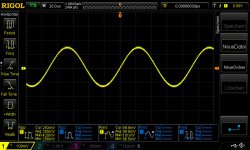
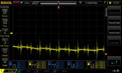
11khz 100mVrms input on both channels
pic 1 is the input signal on the Lch RCA yellow amp off
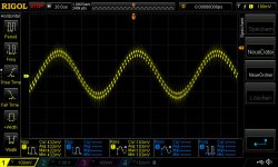
pic 2 is the input signal on the Lch RCA yellow amp on
--> what happened here?? why is the input signal destroyed..scattered???
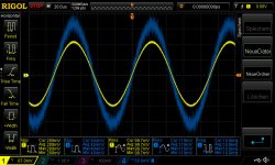
pic 3 is the input signal on the Lch RCA yellow amp off blue is the signal on pin 1 of the opamp
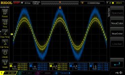
pic 4 is the input signal on the Lch RCA yellow amp on blue is the signal on pin 1 of the opamp
both opamp doing the same
chris
Hi
after a short comparison of the opamp 4562 and the 49720 i found that the 49720 fits very good. i want to have a closer look because the 4562 sounds "hard"...maybe ringing??
at my amp 1 (yes i have 2 amps
) i did some measurements but i found something strange for me.11khz 100mVrms input on both channels
pic 1 is the input signal on the Lch RCA yellow amp off
pic 2 is the input signal on the Lch RCA yellow amp on
--> what happened here?? why is the input signal destroyed..scattered???
pic 3 is the input signal on the Lch RCA yellow amp off blue is the signal on pin 1 of the opamp
pic 4 is the input signal on the Lch RCA yellow amp on blue is the signal on pin 1 of the opamp
both opamp doing the same
chris
Attachments
Hi
just to complete my findings...
here is a pic from this caps...what company is that...what about the quality...i dont know this label
thx chris
post 36..these bipolar 2,2µF caps at pin 4+5
some body know this brand ??
Last edited:
pic 1 is the input signal on the Lch RCA yellow amp off
pic 2 is the input signal on the Lch RCA yellow amp on
--> what happened here?? why is the input signal destroyed..scattered???
That looks like a stray high frequency rectangle (radio?) interference. That could come from the outside but if you say it's also on the input, it's also possible the amp IC is defective. To exclude that, switch the input L+R. If it persists, it's located within the amp.
Put some ferrites right next to the OPamp inputs. Murata offers nice 0402 ones with 1k impedance. (Not the solution but will help somewhat)
The LM4562 is a bipolar input opamp and prone to RF EMI demodulation as seen here. Ferrites may/will help to improve PSRR here. If the input layout isn't well made (unsymmetric) things are getting worse.
Btw. have you monitored the opamps supply rail directly at the local decoupling cap?
The LM4562 is a bipolar input opamp and prone to RF EMI demodulation as seen here. Ferrites may/will help to improve PSRR here. If the input layout isn't well made (unsymmetric) things are getting worse.
Btw. have you monitored the opamps supply rail directly at the local decoupling cap?
Last edited:
After reading about this little amp for just 25$, I gave it a shot at eBay. Today after 10 days, it arrived. It´s for my daughters first own flat, don´t want her to listen to crappy plastic speakers.
Power is from a HP Laptop 19Volt 3.15Amp SMPS, by the way.
I´m not the greatest fan of OP amp rolling, but the little Breze sounded somehow nasty and in no way impressing out of the box. Really ugly.
As the (unnecessary?) input buffer is readily on a socket, I changed the "TI" label NE5533 IC for the same part, but from a reliable supplier (55 Cent). The first second it started up, the bass was like a loudness switch was pushed.
Now the sound is really impressing, even if the set up with a 500€ Onkyo CD player and some Mission 2-way speakers of the some category does not really fit the price tag of the amp (22€ including postage to Germany). Probably even the RCA cable to the CD was more expensive than the amp.
I listen to it in a quite large living room and my impression of the two chip Breze compared to a good single chip TPA3116 is much tighter, controlled bass. The tiny amp really rocks the house. Finest details seem a little harsh sometimes, but the explosive bass makes up for this. Never heard the Mission so powerful without a subwoofer. Maybe this is because of the 10 paralleled capacitors or the lower output resistance.
It also has this certain extra that makes it hard to keep your feet still while listening. Nice 3-D illusion, too.
Also, it finally made me re-think about the burn in of electronics. It is the 3rd cheap D-amp that definitely improved over the first 2-3 hours of playing. Not just my ears adjusting to crappy sound. I switch to my main system with the same CD from time to time to prevent this.
I just auditioned the first CD I heard with it for a second time and rough edges in voice reproduction, that sounded unpleasant 2 hours ago, are surprisingly gone (Eurythmics Live). Like the singer changed the microphone. Nonsense? Maybe in the future I will let new stuff play for a few hours before judging it´s sound quality.
If you resist the temptation to modify and improve it, except for the fake TI OP-amp, I don't see a way to get something better for comparable money (or even 10 times as much).
There are, sure, many better amps out there, don´t get me wrong, but it is sure good enough for some nice listening, even if your used to quite good gear.
That looks like a stray high frequency rectangle (radio?) interference. That could come from the outside but if you say it's also on the input, it's also possible the amp IC is defective. To exclude that, switch the input L+R. If it persists, it's located within the amp.
yes i guess its the small not well designed layout, because both amp do the same and the all chips are fail its not real. i try with mu metall foil to protect the rca inside the amp without shorting something....no result...
if turbowatch2 can do the same measurements then it would clear that´s the design.
chris
- Status
- This old topic is closed. If you want to reopen this topic, contact a moderator using the "Report Post" button.
- Home
- Amplifiers
- Class D
- New Breeeze Audio TPA3116 2.0 100W dual chip