As i wrote...it was on the very beginning of my YJTPA3255 journey..
chris
I tested Tpa3116 yesterday with 20v supply in pbtl mode. I did not used fixed load but judging from the speaker punch and loudness it was nearly 100watts comparing to other 100w amps i have.
I tested tpa3116 on single layer pcb😅. And there was negligible heat after half an hour working. Gain was 36db.
So i was wondering if i design my own board and it qualifies all the requirements of TI then can TPA3255 achieve 500w mark at 45-48v unclipped?
And what will be heatsink requirements for continuos operation? I will be using it in btl mode and pbtl mode.
proper heatsink...design by doctor...As i learned it must be a mirror clean supa flat polished surface to contact to the pad on the chip
https://www.diyaudio.com/forums/class-d/309813-wrong-tpa3255-27.html#post5486776
https://www.diyaudio.com/forums/class-d/309813-wrong-tpa3255-27.html#post5486776
Will that much heatsink be appropriate?proper heatsink...design by doctor...As i learned it must be a mirror clean supa flat polished surface to contact to the pad on the chip
https://www.diyaudio.com/forums/class-d/309813-wrong-tpa3255-27.html#post5486776
Will that much heatsink be appropriate?
i am not a developer so i think doctor is well know what he is doing and designing.
if you compare the roiginal TI EVM boards you will see the appropriate heatsink
i am not a developer so i think doctor is well know what he is doing and designing.
if you compare the roiginal TI EVM boards you will see the appropriate heatsink
Ok will see
Will that much heatsink be appropriate?
You may get away with a smaller heatsink, depending on switching-frequency, supply voltage, output peak power and crestfactor.
higher fsw -> more heat
higher supply voltage -> more heat
higher peakpower with low crest-factor -> more heat
It is possible to run a 3255 at high power with a fan-supported 40x40mm heatsink only. Running fanless needs much more "heatspreading" and some external airflow.
I want 400w rms in 4ohm btl or 2ohm pbtl. I will run it at 400khz above or at 40volts.
Now what do you say, how much heatsink will be required without fan?
Last edited:
...loop reaction at SMPS
following the advice by FF post #357
(Amplifier specific) Use the amplifier with the intended (dummy!) load. The test generator (input) must be able to run in "burst"-mode. Adjust the test generator burst amplitude such that the amplifier output is at a defined output power level. Suggested 50% of full output power and 100Hz frequency. Then run no input signal <-> input signal for defined output power and watch how the SMPS output voltage sags every time a signal burst starts. The response time is the time until the voltage no longer sags.
 i try to made a burst on my freq.generator with 700mVrms and 100Hz into the amp. amp is loaded with 8R both channels.
smps is the LRS150-24 set to 28,7V
with 1cycle burst its not strong enough, because i get just shortly about 300mA out (DMM shows this)
with 10cycles i got between 300mA and 2,3Amps DMM
with 5cycles i got 300ma to 1,4amps out
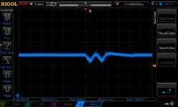
is the reaction time about 20msec? at 10ms overshoot and at 20ms back to the voltage? ....pic 2
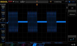
pic 1 input voltage 10 cycles 700mVrms 100Hz
pic 2 1 cycle differential probe directly on V+ and V- of the smps
how to intepret the other cycles? which reaction time
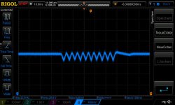
pic 3 5 cycles
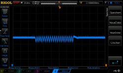
pic 4 10 cycles
thanks chris
following the advice by FF post #357
(Amplifier specific) Use the amplifier with the intended (dummy!) load. The test generator (input) must be able to run in "burst"-mode. Adjust the test generator burst amplitude such that the amplifier output is at a defined output power level. Suggested 50% of full output power and 100Hz frequency. Then run no input signal <-> input signal for defined output power and watch how the SMPS output voltage sags every time a signal burst starts. The response time is the time until the voltage no longer sags.
i try to made a burst on my freq.generator with 700mVrms and 100Hz into the amp. amp is loaded with 8R both channels.smps is the LRS150-24 set to 28,7V
with 1cycle burst its not strong enough, because i get just shortly about 300mA out (DMM shows this)
with 10cycles i got between 300mA and 2,3Amps DMM
with 5cycles i got 300ma to 1,4amps out
is the reaction time about 20msec? at 10ms overshoot and at 20ms back to the voltage? ....pic 2
pic 1 input voltage 10 cycles 700mVrms 100Hz
pic 2 1 cycle differential probe directly on V+ and V- of the smps
how to intepret the other cycles? which reaction time
pic 3 5 cycles
pic 4 10 cycles
thanks chris
Attachments
400W !
with an efficiency about 90% you have still about 40W dissipation = ...you have to look what class A friends are doing
4U x300mm / 400mm heatsink
Total heatsink size should have space of 400mm at least, right?
Total heatsink size should have space of 400mm at least, right?
this is the case what is recommended for Class A e.g. F5 AMP
Dissipante 04/400B 4U 4mm ARGENTO
I would not care about 0.5V peak-to-peak around 28V=
ok. i want to know are these measuremnts technical ok. i could play around the burst mode with delay and cycles to push the smps harder-the input freq. could be changed from 100Hz to something that hurts = 20hz...
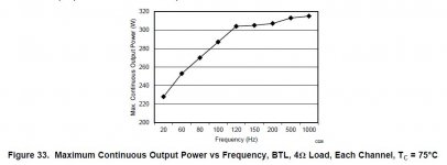
see datasheet figure 33
this test is done at an original board with this big fat strange ESR caps (elna or sanwah)
Attachments
following the advice by FF post #357
(Amplifier specific) Use the amplifier with the intended (dummy!) load. The test generator (input) must be able to run in "burst"-mode. Adjust the test generator burst amplitude such that the amplifier output is at a defined output power level. Suggested 50% of full output power and 100Hz frequency. Then run no input signal <-> input signal for defined output power and watch how the SMPS output voltage sags every time a signal burst starts. The response time is the time until the voltage no longer sags.
smps is the LRS150-24 set to 28,7V
with 1cycle burst its not strong enough, because i get just shortly about 300mA out (DMM shows this)
with 10cycles i got between 300mA and 2,3Amps DMM
with 5cycles i got 300ma to 1,4amps out
is the reaction time about 20msec? at 10ms overshoot and at 20ms back to the voltage? ....pic 2
pic 1 input voltage 10 cycles 700mVrms 100Hz
pic 2 1 cycle differential probe directly on V+ and V- of the smps
how to intepret the other cycles? which reaction time
pic 3 5 cycles
pic 4 10 cycles
thanks chris
Good work, Chris.
You can see the signal-bursts causing important disturbance of the supply voltage. The SMPS loop is (slowly) trying to bring the voltage back but the change in load current is constantly bringing it out of balance. My impression is the power line decoupling is preventing voltage swing the most and the loop is rather slow.
The loop reaction time is normally measured with a single load-step. For instance a 0.5A->2A load step which will cause the output voltage to drop for a start. When the loop has managed to stop the drop in voltage and started returning it to rest-value, you have a measure for the loop reaction time.
A variation in the supply voltage will affect THD but will in part be compensated by the amplifier regulation loop. As Voltwide concludes, do not worry too much - it is inherent in the supply design.
Would it be possible to do the same test with a board where you have replaced the power line decoupling capacitors with better ones? That would show how important the quality of the power line decoupling capacitors is.
Last edited:
this is the case what is recommended for Class A e.g. F5 AMP
Dissipante 04/400B 4U 4mm ARGENTO
I did not understand you. Is it right or wrong?
Good work, Chris.
You can see the signal-bursts causing important disturbance of the supply voltage. The SMPS loop is (slowly) trying to bring the voltage back but the change in load current is constantly bringing it out of balance. My impression is the power line decoupling is preventing voltage swing the most and the loop is rather slow.
The loop reaction time is normally measured with a single load-step. For instance a 0.5A->2A load step which will cause the output voltage to drop for a start. When the loop has managed to stop the drop in voltage and started returning it to rest-value, you have a measure for the loop reaction time.
A variation in the supply voltage will affect THD but will in part be compensated by the amplifier regulation loop. As Voltwide concludes, do not worry too much - it is inherent in the supply design.
Would it be possible to do the same test with a board where you have replaced the power line decoupling capacitors with better ones? That would show how important the quality of the power line decoupling capacitors is.
The topic is not just to do my exercise in learning about smps. it is the strange thing that my LRs350-36 smps is better at 8R speakers then the LRs150-24
Would it be possible to do the same test with a board where you have replaced the power line decoupling capacitors with better ones? That would show how important the quality of the power line decoupling capacitors is.
yes this is my plan today
.....i mean evening...after cookies and Punsch I did not understand you. Is it right or wrong?
as doctor and i mentoied.
you need a heatsink with less then 2W/K ---> big heatsink.
e.g.
Dissipatori
as doctor and i mentoied.
you need a heatsink with less then 2W/K ---> big heatsink.
e.g.
Dissipatori
Got it. A really big heatsink.
- Home
- Amplifiers
- Class D
- What is wrong with TPA3255?