No, of course its not 'proof', its too early days for that. Its an interesting result which calls for further experiments. I do intend to do some in respect of the 'too low PSRR hypothesis' because to do science, all hypotheses need to be testable.
As for whether the designers 'do it properly' - it hinges on what 'properly' means. To TI, 'properly' means achieving the target measurements (THD+N in particular). However to a large number of listeners here, 'properly' means sounding as good as they can get it. No contradiction, just differing aims. So what does 'properly' mean to you?
Well, what i mean is, that "cap rolling" does "improve" SQ for decades with (mostly) no scientific background/proof. SQ is so much subjective and biased that, to me, alot of people hear an improvement/benefit just because there must be something and it costs them some money. Some mods are really expensive for an subjective improvement. My personal opinion is, if it can't be measured in some way on properly interpreted afterwards, it is some kind of snake oil. But this is not meant to offend anyone who "believe in".
Does 'everyone' in scare quotes here not really mean everyone? What benefit would a vendor/designer like to see ? I ask you because clearly you are both. Adding more capacitance on AVDD isn't going to degrade your measurements, merely give an increment on your BOM cost. But if you're a vendor defining a 'proper' design as one with certain measurements, you're not going to see any benefit of increasing your BOM.
With "everyone" i mean people who aren't into the details that much. Not to offend anyone here as well. I want to make clear that i'm not a vendor, but a hobbyist. To be on par, adding more capacitance on AVDD may degrade reliability due to not limited dI/dT at startup. It also affects loop bandwidth of the internal LDO which actually is unknown. Next, i can't understand, how stereo separation will get improved if there's no separation in the supply section where the capacitance is added. I have no problems adding costs to the BOM as hobbyist, but if they wont help/improve anything, they aren't needed. My actual 32XX design also does have some parts populated which don't add much benefit to the overall performance but are there "because textbook". I.e. output capacitance/buffering of the DCDC-converter rails with the help of electrolytics. As the converter runs at frequencies where electrolytics aren't much effective at all, the benefit is questionable. All they do is to influence loop-bandwidth at some extent. Taking PSRR and additional local decoupling into account, they most can likely be omitted. Next, the analog front-end does feature an HF-shielding, which does help on EMI interference from 3G/4G/WiFi coupled in and get demodulated for ranges closer than 10cm to the inputs. Benefit? yes! Real world problem? Most likely not.
")
Parts i "believe in" SQ improvement "because textbook" are .5% 25ppm thin-film resistors in the analog-frontend to keep the symmetry of the diff-stage as close as possible. Those i use: "RR0510P-104-D"
Edit:
Every additional capacitor is an additional (kind of) antenna which is prone to catch some HF from the switching notes. We've seen this i.e. here:
What is wrong with TPA3255?
I get the impression you've not been following along. PSRR measurements I agree aren't hard to do, just time-consuming.Quote:
(Beside the fact that most “cap rollers” never do any measurements) PSRR measurements at AVDD shouldn’t be that hard to do on the EVM if adding caps is that simple anyway. if i don’t split the supply for strep sides, how can stereo image/separation get improved, the “influence” path is still there. All what happens here is to slow down the regulation bandwidth of the internal LDO and force electromigration to degrade the silicon. I wouldn’t call this a mechanism.
I still don't get the "mechanism" involved you're refering to.
Its me who's not following you now. Input filters are for common-mode noise suppression (if we're talking about the same input filters). Can't see how CM noise is affected here.Quote:
For the part of ripple reflection i mean it in a way that noise not only conducts this the output but also to the input (or source). That’s why switching power supplies got a filter also on the input, not only for power factor correction.
I'm refering to effects like the ones shown on page 10ff:
https://flex.com/sites/default/files/AN323_Input Filter Design_FlexTS.pdf
Last edited:
Well, what i mean is, that "cap rolling" does "improve" SQ for decades with (mostly) no scientific background/proof. SQ is so much subjective and biased that, to me, alot of people hear an improvement/benefit just because there must be something and it costs them some money.
I can't for the life of me see a point to cap rolling. I've not engaged in it, I'm unlikely to ever engage in it. But strange things might happen. What I'm suggesting here in terms of decoupling isn't to be confused with cap rolling. I don't care about particular cap brands, only measurements like ESR when it comes to decoupling caps.
For me cap-rolling is just a harmless leisure activity with no benefit to understanding or progress in audio design.
Some mods are really expensive for an subjective improvement. My personal opinion is, if it can't be measured in some way on properly interpreted afterwards, it is some kind of snake oil. But this is not meant to offend anyone who "believe in".
So it would appear you're a believer - at least in audio snake oil
I don't share your cynicism, whilst there is a whole heap of what I might call 'subjectivist nonsense' in audio, there's also such a thing as better SQ. That's not just my belief, its my experience too. Of course better SQ can be measured, just that the measurements aren't sufficiently developed to demonstrate it.OK my mistake, I'd taken you as a vendor.With "everyone" i mean people who aren't into the details that much. Not to offend anyone here as well. I want to make clear that i'm not a vendor, but a hobbyist.
Yes, both good points.To be on par, adding more capacitance on AVDD may degrade reliability due to not limited dI/dT at startup. It also affects loop bandwidth of the internal LDO which actually is unknown.
If by 'stereo separation' you mean a crosstalk measurement then sure, I can't understand that. But that's not what we've been talking about here, rather the extra capacitance gives subjective improvements. Which presumably you take to be snake oil (based on what you wrote above) - that's your choice and I have no issue with you making that choice.Next, i can't understand, how stereo separation will get improved if there's no separation in the supply section where the capacitance is added.
Does 'anything' include subjective impressions? I take it from what you've written so far your answer is likely to be 'no', in which case you'd be daft to add extra capacitance to your BOM.I have no problems adding costs to the BOM as hobbyist, but if they wont help/improve anything, they aren't needed.
Let me outline it again see if more words helps in any way. With a classAB output stage (as used internal to the TPA3255 signal processing), the draw from the power supply is modulated with signal. If the PSRR of the other circuitry sharing the same rail is sufficiently high then this won't matter but since I (and others) hear improvements from lowering the supply impedance it tends to indicate the PSRR isn't sufficient for good subjective results. I hear the biggest improvement from lowering the impedance on high crest factor music - orchestral violins for example become so much more life-like. For those who only listen to heavily compressed material I'd guess the improvement will be smaller. But that's just conjecture.I still don't get the "mechanism" involved you're refering to.
Now i got it. So for the mechanism to further explain regarding PSRR informations regarding OTA implementation is needed, i.e. like shown here:
http://rincon-mora.gatech.edu/research/gtac/gtac_s3f.pdf
The usual links given:
http://www.analog.com/media/en/technical-documentation/application-notes/AN-1120.pdf
Regarding supply seperation:
I remember TI seperated VDD and GVDD with 10uH inductors initially but then went back to simple resistors as they showed better performance and where less prone to EMI pickup.
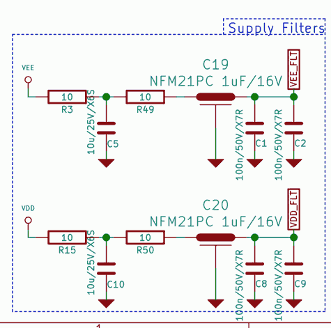
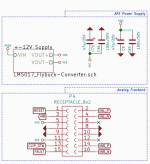
This isn't restricted to capacitance, but let me show you my decoupling path for the AFE:
Decoupling at LM5017 input/outputs:
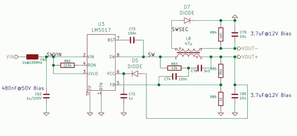
This is done locally with a concentrated GND plane connected to global GND at the GND-pad of the input supply decoupling capacitor. LM5017 is equipped with LC-filter input. fSW is 620kHz.
in distance of 3cm there is local decoupling via 47uF at the AFE connector - this cap is of questionable value as it isn't effective at switchers fSW but in the audio range.

On the AFE module itself there's a 2 stage RC-filter with 2nd-stage feed-trough cap (X2Y) and finally local decoupling at the opamp itself.
So for the mechanism to further explain regarding PSRR informations regarding OTA implementation is needed, i.e. like shown here:http://rincon-mora.gatech.edu/research/gtac/gtac_s3f.pdf
The usual links given:
http://www.analog.com/media/en/technical-documentation/application-notes/AN-1120.pdf
Regarding supply seperation:
I remember TI seperated VDD and GVDD with 10uH inductors initially but then went back to simple resistors as they showed better performance and where less prone to EMI pickup.
Does 'anything' include subjective impressions? I take it from what you've written so far your answer is likely to be 'no', in which case you'd be daft to add extra capacitance to your BOM.Quote:
I have no problems adding costs to the BOM as hobbyist, but if they wont help/improve anything, they aren't needed.
This isn't restricted to capacitance, but let me show you my decoupling path for the AFE:
Decoupling at LM5017 input/outputs:
This is done locally with a concentrated GND plane connected to global GND at the GND-pad of the input supply decoupling capacitor. LM5017 is equipped with LC-filter input. fSW is 620kHz.
in distance of 3cm there is local decoupling via 47uF at the AFE connector - this cap is of questionable value as it isn't effective at switchers fSW but in the audio range.
On the AFE module itself there's a 2 stage RC-filter with 2nd-stage feed-trough cap (X2Y) and finally local decoupling at the opamp itself.
Attachments
Last edited:
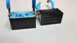
Guys, it is a really bad idea to use roll-type Wima as LC filter or as decoupling for class D. Sometimes even MLCC X7R(with 3-5 times higher voltage rating, 1210 1u/100V for 25VDC is ok) could be better regarding THD/Noise/EMI(of course if the THD+N related to EMI, that's pretty common thing). The optimal cap for output LC is stacked film cap, ideally if SMD one. I see rolled film caps like those glamour-pinky Wima in many wrong cases such as SMPS/classD/DAC 3.3V rails etc no idea who made that mistake so popular.
Well, stacked film exist also in THT variant, i use TDK which is supposed to be in stacked configuration. SMT film is very delicate to solder and can/will make trouble if convection reflowed with components from much higher thermal mass like (huge output) inductors. To overcome this, vapor phase reflow soldering is needed. Biggest problem is shifting capacitance and tand. I prefer THT film or 250V MLCC at this place.
@IVX, are you referring to the much lowered dV/dT rate for most Wima caps thatarent pulse capable and the fact that roll-type is prone to „suck in“ HF/RF/EMI?
@IVX, are you referring to the much lowered dV/dT rate for most Wima caps thatarent pulse capable and the fact that roll-type is prone to „suck in“ HF/RF/EMI?
I wonder where you see rolled wima tht caps. Which series do you refer to?Guys, it is a really bad idea to use roll-type Wima as LC filter or as decoupling for class D. Sometimes even MLCC X7R(with 3-5 times higher voltage rating, 1210 1u/100V for 25VDC is ok) could be better regarding THD/Noise/EMI(of course if the THD+N related to EMI, that's pretty common thing). The optimal cap for output LC is stacked film cap, ideally if SMD one. I see rolled film caps like those glamour-pinky Wima in many wrong cases such as SMPS/classD/DAC 3.3V rails etc no idea who made that mistake so popular.
I wonder where you see rolled wima tht caps. Which series do you refer to?
in my constructions may by?
who knows?in my constructions may by?
What AVDD issue?
i ask at #401
then an expert discussion started..
.
i am interested in some experience.
Last edited:
amp light ...next step
Hi
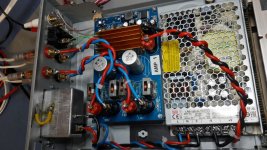
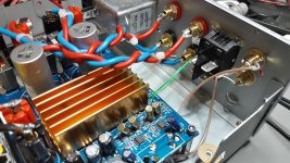
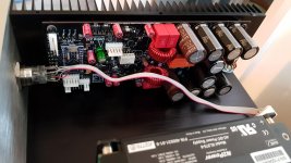
some photos from my amp light in the final installation
the amp board is still not my final.
i want to try different output filter according to the Ti designer.
as written in post #403
sounds fine.
i ordered new Ad8599...will see..
Hi
some photos from my amp light in the final installation
the amp board is still not my final.
i want to try different output filter according to the Ti designer.
as written in post #403
sounds fine.
i ordered new Ad8599...will see..
Attachments
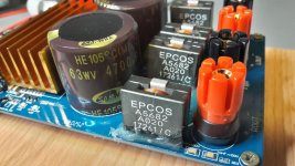
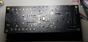
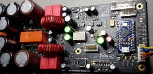
new board with muse caps
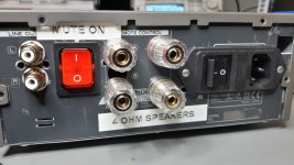
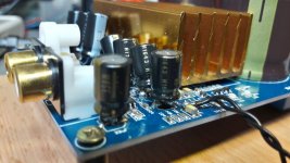
i changed the input all caps (nichicon muse = 10µF not easy because are bigger)and the regulator caps.
output caps are for 4 ohm speakers = 7µH Epcos and under the board 680nF TDK caps, original opamp ST TL072
after more the 70 hours "burn in" of this board sounds best for me.
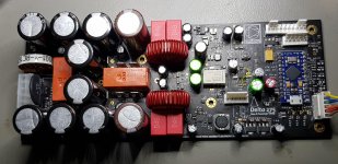
@opamp
i try other board with new opamp ad8599 and this board is not working too.
i do not think a am not able to solder, maybe bad luck and all opamps are defect? these are from digikey?
i changed the input all caps (nichicon muse = 10µF not easy because are bigger)and the regulator caps.
output caps are for 4 ohm speakers = 7µH Epcos and under the board 680nF TDK caps, original opamp ST TL072
after more the 70 hours "burn in" of this board sounds best for me.
@opamp
i try other board with new opamp ad8599 and this board is not working too.
i do not think a am not able to solder, maybe bad luck and all opamps are defect? these are from digikey?
Attachments
My Mono Blocks
See below my home grown TPA3255 Monoblocks.. Must admit it took me two goes to get the PCB right but boy to they sound awesome. seven months of hobby time well spent
See below my home grown TPA3255 Monoblocks.. Must admit it took me two goes to get the PCB right
but boy to they sound awesome. seven months of hobby time well spent Attachments
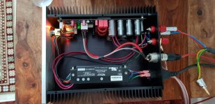
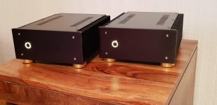
Very impressive work! By hand - you must have a very steady hand.
And a good magnifying glass lol..defo worth the effort
- Home
- Amplifiers
- Class D
- What is wrong with TPA3255?