Desolder the opamps and ground both TPA inputs with the coupling caps in place. if noise is gone, it comes from the frontend. If noise is still there, you fried the input stage in the TPA which usually happens with more than 9V on each input pin.
thanks doctor for your hint...i will try.
but i guess its a skill problem by myside....
") because i start at a other board without wrong soldering of the opamps. and its the same.
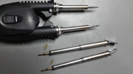
because i start at a other board without wrong soldering of the opamps. and its the same.pic 1 my desoldering smd tool.
the big (buttom) is for soic. i had the problem that this tool pic up the 22pf caps near the opamp and its was to late if i realise this. so this smal 22pf caps are sticking at the soldering tool full with tin-solder. so i have to use my 22pf from the box.
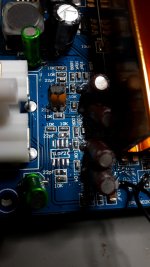
pic 2 wrong label
here you can see the label = "TL02" is other way round. the marking is correct..this was my first bad if you look at late night just on the label.
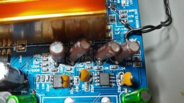
pic3 final change of the opamps-- left loud noise right
Question
could that be that the sensitivity of the AD8599 is higher for feedback loop. i meant the 22pf is too less-should i use 47pF???
Attachments
Hi Emilvv
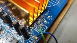
you ask about the reset--> mute switch of this YJ TPA3255 board:
here in the developer thread you will find: post 679 page 68.
TPA3255 - all about DIY, Discussion, Design etc.
my proposal is to read all the pages...yes its hard but you will learn a lot!
Hi emilv
you request the origianl soldering on my boards for the mute switch....here it comes...
chris
Attachments
Hi FF
Hi Doctor
i can partly follow your discussion
is the time of the "smps reaction" measureable? or is a factor missing in the datasheet. how can i do a test?
my intepretation is=> as fast your caps are (very low ESR) and the capacity to upload the cap is not to high --> the smps will not be affected.
@LRS 150-24V
As my protocol showed at 4 ohms load (#343) that i get 5,75amps. therefore the rated current of 6,5 is not achivable with 24V setup without load.
so for me i will try to trimm the SMPS to e.g. 26V get the max current of 6,5 amps(maybe slightly more) at 4 ohms load.
hi
it setup my LRS150-24 psu´s to the max without hickup at 4 ohm resistive load directly at the terminals- without big caps (as discussed)
LRS-150-24 psu 1
setup 28,07V it psuh 6,84A = 192WATT
LRS-150-24 psu 2
setup 29,06V it psuh 6,98A = 200WATT
Chris, what is your thoughts if using higher voltage on TP325x?:
LRS-150-36 psu 1, setup 32V on TPA3250 (eg. FX502Spro) for 4 Ohm Spkr ?
hi forestsgump
As you know i did the configuration for 24V input voltage- so the LM317 was set to the correct setup = 3-4V margin = 20V operation for the opamps.
generally the 32V is ok for tpa3250 and the caps (35V...if they are not fake!!)
power in 4 ohm speaker is for me better to use 24V because you can pull 6,5 amps out of this small psu with 150W .
P=U*I = > P = I^2 + R = > current per channel is about 3,3 amps
3,3^2 *4 = 43,5 Watt per channel
to setup the psu to 28V its able to psuh more current before hickup mode.
chris
pic 2 wrong label
here you can see the label = "TL02" is other way round. the marking is correct..this was my first bad if you look at late night just on the label.
pic3 final change of the opamps-- left loud noise right
Question
could that be that the sensitivity of the AD8599 is higher for feedback loop. i meant the 22pf is too less-should i use 47pF???
Pin 1 indicator is what counts, not labeling. That's why i don't use labeling at all.
The AD8599 is stated to be unity gain stable, but give it a try and solder 1n in place of 22p to see it changes. Well, if they're unstable in this configuration it should be sufficient to just touch the caps leads. Do you know what ceramics yours are made from? I'd only trust NP0/C0G there. Those "oldisch" leaded cercaps might be Y5V is old stock, which is a NONO here.
In looking a the TI 3255EVM manual, I discovered they are using a single +12V
to power the 5532. 3E is doing likewise with their NJM4580 front end op-amp.
This is essentially giving it only -/+6V rails. Most of the published specs for these
op-amp are based on -/+15V rail. I have to wonder how optimal the front
end is running at < 50% of its rail and without the benefit of wide band
regulation like (HxR style regulator).
Without the proper rails and regulation, throwing the $10 AD8599 opamp may
do nothing to SQ.
I have been listening to both the stock version of the 3e and TI EVM boards.
They have different sonic qualities and are providing hours of comparative listening.
I am running a good 500W (setup for 51VDC) SMP from Connex. This has
improved the listen-ability a great amount.
NCore NC400 has nothing to worry about from the two 3255 examples.
thanks doc !
if i am not totally stupid for soldering ......
i wonder that sybic wrote nothing about this.
yes this 22pF caps are normal stlying..
business trip...maybe end of the week...
to make it more clearer:
sybic did his surround amp with 3 boards and he wrote nothing about problems with the original 22pF + Ad8599 or Performance problems (50% rail)
Last edited:
This is essentially giving it only -/+6V rails. Most of the published specs for these
op-amp are based on -/+15V rail. I have to wonder how optimal the front
end is running at < 50% of its rail and without the benefit of wide band
regulation like (HxR style regulator).
Plenty of opamps run fine on +/-6V with only slight changes to their parameters. The AD8599 is one such - its fully characterized for +5/-5V operation and only gives up a couple of volts of slew rate at the lower voltage that I can see. GBW is unchanged.
Without the proper rails and regulation, throwing the $10 AD8599 opamp may do nothing to SQ.
I agree about the necessity for high quality power rails - have you provided external regulation for the TPA3255's signal processing rail voltage? I suspect if you do, it'll leave the NC400 behind. My own board improved immensely from just adding additional caps to that rail, regulation I've yet to try as it requires some trickery to override the internal reg.
Hi all
I'm thinking to give a try at one of those TI Evm or 3E-audio boards but I've got a question.
I seen on TI EVM and 3E-Audio datasheet that input impédance is 10k, that's set with input and feedback loop on opamps, as 10k is a bit low for my setup, do you think changing those resistors (and feedback caps accordingly) will reach the noise up to high ?
to avoid using one more opamp between my passive LDR volume and that amp i would like to reach it to 47k at least.
any advice on that point ?
best regards
Has anyone here actually tried improving the 12V rail? Was there much SQ improvement?I agree about the necessity for high quality power rails - have you provided external regulation for the TPA3255's signal processing rail voltage?
The EVM uses an LM5010A switching reg to step down the supply voltage to 15V, then on to an LM2940 linear regulator to provide 12V.
I suppose a basic upgrade would be to divert the existing 15V to a better 12V regulator, such as - LT3042/LT3080/ADM7150/TPS7A4700 etc.
And a more advanced upgrade would be to give this new regulator its own transformer and rectifier, such that it becomes a completely separate supply.
But is any of this worthwhile?
- Home
- Amplifiers
- Class D
- What is wrong with TPA3255?