... Been a while. Finally got my 2xTPA3255 EVM setup in a box, with dual mono psu, but there's white noise. I got sensitive speakers, so the noise is somewhat intrusive.
They sound very nice, just can't handle the noise, so I put it back on the shelf for the time being.
Tried numerous pre-stages, same thing.
Any hints or tips?
And there's pop on startup, not a huge issue, but it's there.
They sound very nice, just can't handle the noise, so I put it back on the shelf for the time being.
Tried numerous pre-stages, same thing.
Any hints or tips?
And there's pop on startup, not a huge issue, but it's there.
... Been a while. Finally got my 2xTPA3255 EVM setup in a box, with dual mono psu, but there's white noise. I got sensitive speakers, so the noise is somewhat intrusive.
They sound very nice, just can't handle the noise, so I put it back on the shelf for the time being.
Tried numerous pre-stages, same thing.
Any hints or tips?
And there's pop on startup, not a huge issue, but it's there.
Wiring is very important. Can you share detailed pictures
Hi Chris,
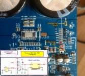
I had a quick look at the circuit proposed by "The Doctor" and The Doctor is clearly the best to advise a solution to your problem.
My immediate doubt was to the 4V7 zener that, if used, will result in a voltage in the order of 4.7V on a /RESET input that as "absolute maximum" allows 4.2V (3.3V logic)! I may have overlooked a detail but else, complaining about performance when the operation is above the absolute maximum rating could seem illogical. Perhaps a 3V3 or 3V9 Zener?
As Zener tend to limit quite “softly” quite before they reach their hard knee point, 3V3 will not work nicely as the threshold point will reached current and temperature dependent. The VDD pin at TPS3803 can handle a maximum voltage of 7V. The RESET output voltage is then roughly VDD-0.1V. BUT when using the correct resistor divider tightly bound to supply voltage, the voltage seen by the TPS never reaches 4.2V which is the maximum input voltage fr the TPA32XX Reset input. Additionally the current into pin is limited by the upper resistor dividers value. (Noob proofness of course would need an additional Zener at the TPA32XX Reset line)
Last edited:
I will when I get home from work.
Was thinking I should flip the heatsink with the 2 x SMPS firmly attached, maybe a little bit of distance and metal would fix it.
Grounded the chassis, even tried some of the old gnd tricks to isolate noise, as I originally assumed it was my source, but no. Moving the signal wires about did a little, but not much.
I *could* put the signal wires under a steel shield, but have to make it first.
Hmmm... Maybe I could take home a little bit of GUR36 half tubing...
As Zener tend to limit quite “softly” quite before they reach their hard knee point, 3V3 will not work nicely as the threshold point will reached current and temperature dependent. The VDD pin at TPS3803 can handle a maximum voltage of 7V. The RESET output voltage is then roughly VDD-0.1V. BUT when using the correct resistor divider tightly bound to supply voltage, the voltage seen by the TPS never reaches 4.2V which is the maximum input voltage fr the TPA32XX Reset input. Additionally the current into pin is limited by the upper resistor dividers value. (Noob proofness of course would need an additional Zener at the TPA32XX Reset line)
Thanks, you have taken account of it.
I will when I get home from work.
Was thinking I should flip the heatsink with the 2 x SMPS firmly attached, maybe a little bit of distance and metal would fix it.
Grounded the chassis, even tried some of the old gnd tricks to isolate noise, as I originally assumed it was my source, but no. Moving the signal wires about did a little, but not much.
I *could* put the signal wires under a steel shield, but have to make it first.
Hmmm... Maybe I could take home a little bit of GUR36 half tubing...
Pictures and a wiring diagram would help. Are all your heatsinks isolated from GND?
The heatsink with the two SMPS is grounded, through the chassis. I tried without gnd first, was a bit worse.
Will have to wait a little before I can post that picture, our 6 year old just threw up a lot...
It really stinks downstairs where the amp is, and I am trying to avoid getting sick.
Does not hurt being overly hygienic right now.
Will have to wait a little before I can post that picture, our 6 year old just threw up a lot...
It really stinks downstairs where the amp is, and I am trying to avoid getting sick.
Does not hurt being overly hygienic right now.
The heatsink with the two SMPS is grounded, through the chassis. I tried without gnd first, was a bit worse.
Will have to wait a little before I can post that picture, our 6 year old just threw up a lot...
It really stinks downstairs where the amp is, and I am trying to avoid getting sick.
Does not hurt being overly hygienic right now.
Any shielding may be helpful to reduce hum. But you wrote explicitely "white noise" - and this normally originated inside the amp or pre-amp.
Could you pls upload a sound sample of your noise? Or, could you measure the noise with ARTA?
Haha, just now tried before Off 3251 by RST, I switched off GVDD and got zero click for Off operation )) It is not too difficult to add one more p-n-p but OMG, I can't believe if it should be so stupid..
No wonder..no GVDD, no switching.
")
Any shielding may be helpful to reduce hum. But you wrote explicitely "white noise" - and this normally originated inside the amp or pre-amp.
Could you pls upload a sound sample of your noise? Or, could you measure the noise with ARTA?
I did not get around to this yesterday because of various circumstances...
Hoping to get the opportunity today.
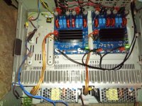
Yes, it comes from the amp, not the pre-stage. Sounds a bit like white noise.
Here's a picture after I flipped over the heatsink, a tiny bit better, but not much.
I'll try switch to the se-600-48 psu just to check.
Edit:
It seems a bit quieter with the 600w psu, but the thing is LOUD, gonna disconnect the fan so I can actually hear anything.
Edit2:
Oh, wow. That is much better. Even less noise on the speaker with no fan, must be some disturbance thing going on.
Still not 100% quiet, but I have to listen for it to notice the noise now. My dawning tinitus is a tiny bit worse, then there's the heat pump fan. But yeah.
Gonna see what happens if I add some caps and diodes.
Attachments
Last edited:
Chris, yes they are earth connected, through the chassis. It was the PSU's.
Changed to a single SE-600-48 and it was much better, at least after I removed the fan.
I am familiar with the various cabling issues. Tried holding the cables in various ways and also having a sheet of steel in between, just to find out which cable placement would work. With the dual mono PSU there seemed to be noise everywhere, some places more than others.
Having signal wires cross power cables can work well enough, provided the cross is perpendicular.
Now I want to add a resistor to the psu fan, just to have a tiny bit of movement in the air. And next is using a better source than the minidsp 2x4. Will try the ADAU1466 EVM board and use optical in to isolate everything as much as possible.
If GVDD<UVP_threshold then all mosfets switching off synchronously or let's say, within 20nS. When the IC switched off by RST pin, the output stage continues switching during 1500uS and nex off not really synchronously. 1st case: I have excellent Off transient as a fast fading LC ringing 60kHz i.e. inaudible. 2nd case: as to me, loud enough click. No one my amp before had such On or Off noise, hence I have to fix that Ti's design defect. The second design defect of Ti is the awfully sounding tpa3251(3255 phase margin even worse!) with post-fb according to slaa788a. My regulated VDD rail is 33VDC and 1% THD power about 130W, however, around 70W at speaker load 3251 starts to produce audible noises as a result of self-oscillation. I've checked clipping of the 3251 with no post-fb network and found it better but still quite bad and I'm sure it makes sound harshness at high levels. For example, TAS5624 has near to perfect clipping behavior, I think these chips were designed by different designers, and 3251 loop gain was set impractically high just for "Ultra-HD" PDF's show off, with crazy low phase margin, and finally the sound quality as a victim.. I very disappointed, and almost give up the 3251 project.No wonder..no GVDD, no switching.
Chris, yes they are earth connected, through the chassis. It was the PSU's.
....
Hi KaffiMan
ok.
if i build my amps a always get the mandatory hint to connect an extra cable from the AC socket to the chassis.
some surface of new (black anodizied...) or old chassis are not really give good contact--> so i scratch on the chassis at the point where the earth should be connected
chris
Chris, all well and good, those PSU's did not have any earth connection to the pcb, the way they where attached to the chassis gave extremely good shield connection to ground, but it did not help at all.
Think I will add a 230v relay to turn on/off both wires to the PSU at the same time.
Think I will add a 230v relay to turn on/off both wires to the PSU at the same time.
doctormord, in my case I see pretty much the same issue with speaker load and no load at all. It is really ugliest clipping ever, try to implement Ti's post-fb app-note to see. Actaually, last night I've got some improvement around clipping but THD at 6.3kHz now is worse - no wonder.. Even caraudio brands(it was JL), which worrying mostly about the BOM cost, pushed me to improve clipping behavior of some amps(tda8954+extra integrator). To be honest, I didn't notice anything wrong with 1kHz harsh near to the clipping but the customer did. I think if I can hear HARSH-CH-CH distortions of the 1kHz sine at 100W level and 92dbWm(that's crazy loud! THD about .5%, the spectrum looks like a noise floor getting up from -150db to -50db + fence of odd harmonics) it is 100.0% not acceptable for all my former customers, and Off clicking as well wouldn't be approved (I remember, customers did push me to reduce On/Off transients which were much less than 3251 has).
- Home
- Amplifiers
- Class D
- What is wrong with TPA3255?