diode test 1
negative lead of the measurement tool (ohm meter set to diode test) on the pin - positive red lead to GND
good board shows 0,6V on BST_A,B, C, D
bad board shows on all 4 BST to GND 0V
diode test 2
red positive lead of the measurement tool (ohm meter set to diode test) on the pin - negative black lead to GND or V+
good shows OL on all 8 measurements
bad board shows at GND OL and on V+ 0,42V
chip dead?!?
Most likely yes. Diode Test 1 is the correct way to test. You may also check the output pins (OUTA-OUTD) like so.
Most likely yes. Diode Test 1 is the correct way to test. You may also check the output pins (OUTA-OUTD) like so.
I am very sorry that i bagder you and voltwide....

Thank you doc to give me feedback.
i desolder at out_ A the coil and the 33nF BST A -still piep between OUT_A and GND = short !!!...so i think this chip is dead.
Last edited:
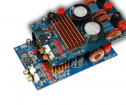
Here's my TPA3255 with Smps300R 38v
<img src="https://i.ibb.co/By87F9L/IMG-20181229-203000.jpg" alt="IMG-20181229-203000" border="0">
<img src="https://i.ibb.co/6sHccf5/IMG-20181229-201537.jpg" alt="IMG-20181229-201537" border="0">
<img src="https://i.ibb.co/YhTN5t4/IMG-20181229-174912.jpg" alt="IMG-20181229-174912" border="0">
<img src="https://i.ibb.co/92syDBT/IMG-20181229-173959.jpg" alt="IMG-20181229-173959" border="0">
<img src="https://i.ibb.co/nBrWMXX/IMG-20181229-125823.jpg" alt="IMG-20181229-125823" border="0">
<img src="https://i.ibb.co/7yWxDvg/IMG-20181229-121705.jpg" alt="IMG-20181229-121705" border="0">
An externally hosted image should be here but it was not working when we last tested it.
An externally hosted image should be here but it was not working when we last tested it.
An externally hosted image should be here but it was not working when we last tested it.
An externally hosted image should be here but it was not working when we last tested it.
An externally hosted image should be here but it was not working when we last tested it.
hi ferchin79
i had the same troubles at the beginning:
make photos and store it from your phone or cam to jpg.
change the size into smaller format
i personally type a name that i know/search the pics easier
insert attachments
upload it !!!!
to find the upload button i have to stretch the window- so you can see the button
wait until upload is finished !
save post
please try it again
chris
...
Thank you doc to give me feedback.
i desolder at out_ A the coil and the 33nF BST A -still piep between OUT_A and GND = short !!!...so i think this chip is dead.
is that correct...
chip dead....?
Sorry if this was brought up before, I've read through this thread back and forth but not in a linear fashion.
I noticed there are two variants of the blue TPA3255 board, the major significant difference being different capacitors. One has electrolytics after input opamp stages and is missing the 3.3V regulator. Electrolytics are more expensive so I'm assuming the other one is newer "optimized" version.
Can anyone chime in on the versions and which is considered "better"? My intention is to use a pair of these boards for biamped speakers in place of TPA3118 for moderate listening levels so power requirements are somewhat low - I think 36V supply will be more than plenty so the step down regulator is fine as is.
Thanks in advance!
Attachments
hi WXN
if i understand you and see the pic´s i can say that i never had board without this little polymer caps.
i bought 1 year ago a blue board with the version of following regulators:
LM2575S -15 and the LM 317. so this regulator is providing the voltage for the opamps and the power chip. not really separated because the LM2575-15 is step down the input voltage to 15V to feed the lm317 input ..then the lm317 is configured to get about 12,7 Volts..this is for the power supply of the opamps and the analog supply of the power chip
as you see in the power chip (TPA3255) datahseet the max input voltage sould not go over 13,2V - so sybic () did a modification of the lm317 down to exact 12V
for testing and try an 8R configuration a bought additionally boards- these boards are with 1 voltage regulator LM2575T-12...so these regulator is providing the voltage for the opamps and the power chip
for my impression with the board i got.......with LM2575T-12 are of a bad quality...soldering is a nightmare because my solder pads are partly away and as you read 1 regulator was dead after some tests...
its existing a black board in the net. i don´t know what for a version it is...
the voltage regulator 3,3v is not existing in my boards...so maybe you have a version 4
blue LM2575S-15 +LM317
blue LM2575T-12
black
blue with AMs3,3 and SMD caps...yours
so i am not able to write you which is better in SQ.
so you have more than 1 board so you can compare....
chris
if i understand you and see the pic´s i can say that i never had board without this little polymer caps.
i bought 1 year ago a blue board with the version of following regulators:
LM2575S -15 and the LM 317. so this regulator is providing the voltage for the opamps and the power chip. not really separated because the LM2575-15 is step down the input voltage to 15V to feed the lm317 input ..then the lm317 is configured to get about 12,7 Volts..this is for the power supply of the opamps and the analog supply of the power chip
as you see in the power chip (TPA3255) datahseet the max input voltage sould not go over 13,2V - so sybic (
) did a modification of the lm317 down to exact 12Vfor testing and try an 8R configuration a bought additionally boards- these boards are with 1 voltage regulator LM2575T-12...so these regulator is providing the voltage for the opamps and the power chip
for my impression with the board i got.......with LM2575T-12 are of a bad quality...soldering is a nightmare because my solder pads are partly away and as you read 1 regulator was dead after some tests...
its existing a black board in the net. i don´t know what for a version it is...
the voltage regulator 3,3v is not existing in my boards...so maybe you have a version 4
blue LM2575S-15 +LM317
blue LM2575T-12
black
blue with AMs3,3 and SMD caps...yours
so i am not able to write you which is better in SQ.
so you have more than 1 board so you can compare....
chris
Last edited:
...... My intention is to use a pair of these boards for biamped speakers in place of TPA3118 for moderate listening levels so power requirements are somewhat low - I think 36V supply will be more than plenty so the step down regulator is fine as is.
Thanks in advance!
my hint for bi amping:
the original coils at the output filter are about 12µ-12,6 µH with about 1,2µF caps...so its about an 8R configuration...this should be fit to the tweeter section
if you use the other coils about 7µH with a 680nF caps you get an 4 R configuration for the subs
yes the 36V power supply should fit for enough power...i use the LRS 350-36. do not exceed the voltage because of the Voltage regulator--> its max is about 40V.
chris
Thank you for the insights, chermann, I don't have any of the boards yet, that was just a compilation of aliexpress photos. I've read through your modifications and schematics - very nice job. My speakers are of inverse impedance though - tweeter is 4ohms and woofer 8 ohms. My understanding is that filter configuration mainly affects the highest frequencies - above 10kHz or so? If so, I should be looking into converting one of the amps to optimize the HF response for 4 ohm loads.
Also, I wasn't aware of boards with only single step-down regulator, some of them on Ali indeed have a blank space in place of the 317. Chinese economy I guess.. What's worse, there is no guarantee that I will get what is in the pictures, they might just send out the "updated" board instead. Lottery
Also, I wasn't aware of boards with only single step-down regulator, some of them on Ali indeed have a blank space in place of the 317. Chinese economy I guess.. What's worse, there is no guarantee that I will get what is in the pictures, they might just send out the "updated" board instead. Lottery
Thank you for the insights, chermann, I don't have any of the boards yet, that was just a compilation of aliexpress photos. I've read through your modifications and schematics - very nice job. My speakers are of inverse impedance though - tweeter is 4ohms and woofer 8 ohms. My understanding is that filter configuration mainly affects the highest frequencies - above 10kHz or so? If so, I should be looking into converting one of the amps to optimize the HF response for 4 ohm loads.
Also, I wasn't aware of boards with only single step-down regulator, some of them on Ali indeed have a blank space in place of the 317. Chinese economy I guess.. What's worse, there is no guarantee that I will get what is in the pictures, they might just send out the "updated" board instead. Lottery
hi WXN
tweeter with 4ohms need no serial resistor?
is the crossover network ready?
lottery...maybe....but sound wise i found nothing different in SQ
1. step....opamp and input caps is a "must" to get better SQ
Last edited:
Yes, I use active crossovers so no need for any passive components between power amplifier and the driver, consequently impedance and sensitivity are not as important
hi WXN
tweeter with 4ohms need no serial resistor?
is the crossover network ready?
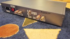
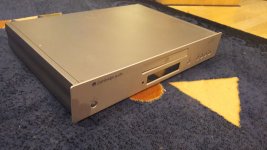
...continued..amps light 2..
good morning...
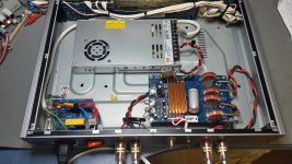
amp light 2 is ready..its continued from post 605
https://www.diyaudio.com/forums/class-d/309813-wrong-tpa3255-61.html#post5632314
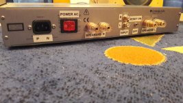
i was a little bit in trouble because the inner dimension high is just 58mm...so i have to change some ideas + add a power switch
its an 8R output filter with the selected original coils that means i use the coils with the bigger values..about 12,9-13,2 µH for my 8R speakers.
opamp 1602, input caps green bipolar muse to the amp + elna silmic 2 to the power chip. original buck regulator but changed 220µH coil and caps. decoupling cap are the gpd
sound very good.
chris
good morning...
amp light 2 is ready..its continued from post 605
https://www.diyaudio.com/forums/class-d/309813-wrong-tpa3255-61.html#post5632314
i was a little bit in trouble because the inner dimension high is just 58mm...so i have to change some ideas
+ add a power switchits an 8R output filter with the selected original coils that means i use the coils with the bigger values..about 12,9-13,2 µH for my 8R speakers.
opamp 1602, input caps green bipolar muse to the amp + elna silmic 2 to the power chip. original buck regulator but changed 220µH coil and caps. decoupling cap are the gpd
sound very good.
chris
Attachments
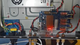
Hi Chris what cap you put near the power input?
Hi
it should be a low esr type 50V in your case 63V with 470-1000µF. my low esr caps are gone at home...
so i use this nice gold shiny caps from nichicon i guess its the uwf serie 50V 220µF rated
pic from your amp?...try it agian
chris


- Home
- Amplifiers
- Class D
- What is wrong with TPA3255?