Hallo All,
So what was the final verdict ? Can this be used for sub duty safely with +-59V rails ?
IRS2092S 500W Mono Channel Digital Amplifier Class D HIFI Power Amp Board + FAN | eBay
")
The 500W (250+250) I bought have low V protection, but I think 59V 8R load is ok. In my case the low V limit was 52V.
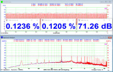
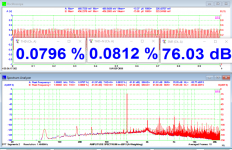
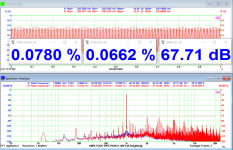
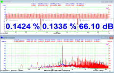
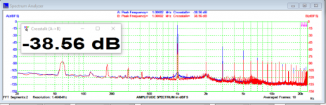
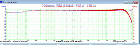
BTW, the measurements achieved with 8R/1kHz 65VDC (regulated source) are below, DHT@1W, @10W, @100W, @200W (onset clipping), crosstalk@10W and FR@10W from left to right. The measurements were done with the board "naked" over the bench, with no shielding nor other cares.
Power on clipping at 1kHz was 210W per channel, efficiency was 93%.
Regards,
Attachments
Last edited:
The 500W (250+250) I bought have low V protection, but I think 59V 8R load is ok. In my case the low V limit was 52V.
BTW, the measurements achieved with 8R/1kHz 65VDC (regulated source) are below, DHT@1W, @10W, @100W, @200W (onset clipping), crosstalk@10W and FR@10W from left to right. The measurements were done with the board "naked" over the bench, with no shielding nor other cares.
Power on clipping at 1kHz was 210W per channel, efficiency was 93%.
Regards,
That is a different amp form the 1st post, correct?
Interesting timing. I just bought a few one of these and hooked one up to a +/- 70V SMPS last night. Tested with an 8 ohm dummy load with a 1 kHz sine wave input. Just before the onset of clipping I measured 41 V RMS or 211 W RMS. That works out to about 116 V P-P which is about 17% under the theoretical limit of the 140 V supply. Not sure if that is expected for an IRS2092 chip but seemed a bit low. I didn't run it that way for more than about 10 seconds since I didn't have any active cooling on my load resistors but it didn't seem like it would quit soon.
Next step is to to test with two amps bridged. That will allow me to see what double the current out of each amp will look like without worrying about bus pumping. If the output voltage stays the same they could _theoretically_ deliver about 850 W.
According to the amp specs I should get 760 W, but those same specs estimated 280 W RMS with 0.1% THD into 8 ohm at +/- 65 V. That doesn't make sense to me as it would require peak voltages greater than the supply rails!
I will post an updated once I have done some more testing.
UPDATE: I did some more testing tonight. I still didn't have active cooling for the load resistors so input was only applied temporarily, but there appears to be minimal output voltage change with a 4 ohm load vs. the 8 ohm load I tested with yesterday.
Output voltage was still about 41 V RMS, meaning each amplifier was producing about 420 W RMS, or 840 W total. I know those are serious numbers because I blew a 10 A 120V AC line fuse protecting the workbench when I drove the amplifiers into clipping. Before everything went dark the scope reported 50 V RMS at the output of one of the modules. I need to setup some cooling fans and a somewhat more permanent setup before doing any longer term load/heat tests but so far so good.
Output voltage was still about 41 V RMS, meaning each amplifier was producing about 420 W RMS, or 840 W total. I know those are serious numbers because I blew a 10 A 120V AC line fuse protecting the workbench when I drove the amplifiers into clipping. Before everything went dark the scope reported 50 V RMS at the output of one of the modules. I need to setup some cooling fans and a somewhat more permanent setup before doing any longer term load/heat tests but so far so good.
Measure the self output noise of the modules - with shortened inputs and 4/8 ohm load.
and the fan on the chip...which noise is he doing if you require such power?
Measure the self output noise of the modules - with shortened inputs and 4/8 ohm load.
Yeah, not great. 1-3 V RMS carrier depending on the frequency. I started another thread here asking if I should care and the consensus seems to be: no.
Aside from the carrier, other noise seems to be low. I plan to hook this up to some speakers soon so I can see how it all sounds in the "real world".
and the fan on the chip...which noise is he doing if you require such power?
This is going to drive a cabinet for a bass guitar so when playing the fans won't be heard. It's the rest of the time I care. Having said that the fans seem surprisingly quiet. I had planned to replace the tiny stock fans with a large "silent" version but I am not sure I will need to.
On the other hand, the fan in the SMPS are insanely loud so I definitely need to replace those!
Smoke and sparks!
Another update: I reconfigured the test setup including connecting the function generator through a balanced preamp, dropping the supply rails to +/- 65 V, and raising the oscillation frequency to around 330 kHz. Re-running some tests shows about a 5 V drop in the RMS output voltage just before clipping which seems reasonable. Re-testing the carrier noise showed it had dropped to about 1 V RMS, which is lower than expected. Not sure I can explain why the drop was that large but it was consistent on both bridged amplifiers.
Next I hooked it up to a real speaker and when I turned on the power all hell broke loose. Smoke and sparks off both amplifier boards, accompanied by a noisy squeal from the speaker. I quickly shut off the power but damage had been done for sure.
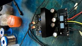
I examined the boards and all the smoke and sparks appeared to come from a resistor, labeled "100" in this picture, adjacent to the center screw terminal:

I checked and that resistor is now open so I removed it and under the chip was the label R36. I measured another new amplifier module and that resistor does read about 10 ohms.
This board seems to be based in the IRAUDAMP7S reference design, but there is no R36 on that schematic. Not too surprising though since this board has a buck converter that also doesn't exist in the reference design.
That said, there is a R30 in the reference design, which is a 10 ohm 1 W resistor, but in the reference design that goes to C13, a 0.1 uF capacitor that doesn't seem to exist on the boards I have. On these boards R36 seems to connect to R21, a small unlabeled chip resistor, which then seems to connect to ground. That makes little sense to me so I might have to start probing with an ohmmeter to see if that is really what is going on.
A test of a few other major components didn't turn up any more damage so I briefly re-powered the amplifiers, this time grounding the inputs, and watched the output on the scope. The amps seem to be putting out a lot of high frequency, high power noise. Nothing audible was coming out of the woofer, except an initial thump and then perhaps some faint static, but I didn't leave it powered long enough to see if anything else exciting would happen.
Hmmm...
Next I un-bridged the amplifiers and connected the speaker to one amplifier and ground. On the other amplifier I connected a dummy load and grounded the input. This seemed to work find and I was able to put a sine wave through the amplifier which came out sounding fine on the speaker.
So...
For some reason it appears the amplifiers went into oscillation when connected to a real speaker (inductive load) instead of the resistive dummy loads I had been using during prior testing. Any ideas what might have been the cause? I don't have any shielding around these boards, nor any shielding around the input wiring. Could the two amplifiers be generating enough RF to interact in some bad way?
Second, any thoughts on what R36 might have been doing? I can probably send some better pictures of the circuit board if it would help.
I have also ordered some 10 ohm 1 W metal film resistors to replace the fried parts. Not sure if they will act like the original but something should be better than nothing, though admittedly I am not sure what they were doing in the first place.
Another update: I reconfigured the test setup including connecting the function generator through a balanced preamp, dropping the supply rails to +/- 65 V, and raising the oscillation frequency to around 330 kHz. Re-running some tests shows about a 5 V drop in the RMS output voltage just before clipping which seems reasonable. Re-testing the carrier noise showed it had dropped to about 1 V RMS, which is lower than expected. Not sure I can explain why the drop was that large but it was consistent on both bridged amplifiers.
Next I hooked it up to a real speaker and when I turned on the power all hell broke loose. Smoke and sparks off both amplifier boards, accompanied by a noisy squeal from the speaker. I quickly shut off the power but damage had been done for sure.
I examined the boards and all the smoke and sparks appeared to come from a resistor, labeled "100" in this picture, adjacent to the center screw terminal:
I checked and that resistor is now open so I removed it and under the chip was the label R36. I measured another new amplifier module and that resistor does read about 10 ohms.
This board seems to be based in the IRAUDAMP7S reference design, but there is no R36 on that schematic. Not too surprising though since this board has a buck converter that also doesn't exist in the reference design.
That said, there is a R30 in the reference design, which is a 10 ohm 1 W resistor, but in the reference design that goes to C13, a 0.1 uF capacitor that doesn't seem to exist on the boards I have. On these boards R36 seems to connect to R21, a small unlabeled chip resistor, which then seems to connect to ground. That makes little sense to me so I might have to start probing with an ohmmeter to see if that is really what is going on.
A test of a few other major components didn't turn up any more damage so I briefly re-powered the amplifiers, this time grounding the inputs, and watched the output on the scope. The amps seem to be putting out a lot of high frequency, high power noise. Nothing audible was coming out of the woofer, except an initial thump and then perhaps some faint static, but I didn't leave it powered long enough to see if anything else exciting would happen.
Hmmm...
Next I un-bridged the amplifiers and connected the speaker to one amplifier and ground. On the other amplifier I connected a dummy load and grounded the input. This seemed to work find and I was able to put a sine wave through the amplifier which came out sounding fine on the speaker.
So...
For some reason it appears the amplifiers went into oscillation when connected to a real speaker (inductive load) instead of the resistive dummy loads I had been using during prior testing. Any ideas what might have been the cause? I don't have any shielding around these boards, nor any shielding around the input wiring. Could the two amplifiers be generating enough RF to interact in some bad way?
Second, any thoughts on what R36 might have been doing? I can probably send some better pictures of the circuit board if it would help.
I have also ordered some 10 ohm 1 W metal film resistors to replace the fried parts. Not sure if they will act like the original but something should be better than nothing, though admittedly I am not sure what they were doing in the first place.
Since the last post was a bit off-topic I started a new thread here:
Fixing [and preventing] a fried Zobel network
Bottom line for this thread:
Yes, it appears that 500 W is believable if thermal and other factors are controlled.
Fixing [and preventing] a fried Zobel network
Bottom line for this thread:
Yes, it appears that 500 W is believable if thermal and other factors are controlled.
Test results
One final update to this thread. I managed to get my bridged amplifier setup working well so ran some tests. Here's the figures, with all voltage/power values listed as RMS:
Power supply: +/- 65 V switching, 1200 W total output
Amplifier carrier frequency: 400 kHz
Load: 8 ohm resistive
Measured carrier residual at output: 0.84 V (per amplifier)
Input signal: 30 Hz sine except for the clipping test which used a 300 Hz sine. This was done to remove excessive power supply sag due to insufficient filter capacitors.
Maximum output before clipping for two bridged amplifiers: 720 W (76 V)
Maximum output with significant clipping (my best guess at 10% THD) for two bridged amplifiers: 1060 W (92 V)
For those that like pictures, here are a few. Unfortunately my old Tektronix scope doesn't support any fancy USB stuff. Does anyone remember GPIB?
Here is a "clean" power waveform, 10 wave average to smooth carrier and ringing artifacts:

Here is the same capture without averaging. This reveals the ringing artifacts near the peaks. Not sure if this is expected behavior for an amp like this or not:

Here is one with significant clipping:

The voltage values on the scope are all after a X10 reduction on the probe, and these are measurements from one amplifier to ground. The bridged amp effectively puts out double these RMS voltages. The number on the bottom left is Vp-p and bottom middle is Vrms.
For reference the modules are rated at 500 W RMS @ 10% THD, or 380 W RMS @ 1% THD into a 4 ohm load. Within reasonable error, those seem pretty accurate. I am pleasantly surprised actually.
The modules ran for several minutes at 400 W RMS bridged (200 W per module) at which point the output level went to about half power for a few seconds before going back to full again. I presume this was over-temperature protection on the IRS2092 kicking in.
Compare that to 720 W RMS bridged output where the modules went 80 seconds before output was reduced.
All of that seems acceptable. For continuous full power significantly better cooling would be required. Even with the stock fans running the heat sinks were uncomfortably hot to the touch. At the more conventional 1/8 power level I suspect these could run continuously.
Regarding efficiency, I measured 1280 W/1640 VA draw on the AC line during the clipping test. That puts total efficiency, including power supply, 83%. Not bad.
Idle (no input) AC line draw was 28 W/52 VA. Definitely no PFC on those supplies!
One final update to this thread. I managed to get my bridged amplifier setup working well so ran some tests. Here's the figures, with all voltage/power values listed as RMS:
Power supply: +/- 65 V switching, 1200 W total output
Amplifier carrier frequency: 400 kHz
Load: 8 ohm resistive
Measured carrier residual at output: 0.84 V (per amplifier)
Input signal: 30 Hz sine except for the clipping test which used a 300 Hz sine. This was done to remove excessive power supply sag due to insufficient filter capacitors.
Maximum output before clipping for two bridged amplifiers: 720 W (76 V)
Maximum output with significant clipping (my best guess at 10% THD) for two bridged amplifiers: 1060 W (92 V)
For those that like pictures, here are a few. Unfortunately my old Tektronix scope doesn't support any fancy USB stuff. Does anyone remember GPIB?
Here is a "clean" power waveform, 10 wave average to smooth carrier and ringing artifacts:
Here is the same capture without averaging. This reveals the ringing artifacts near the peaks. Not sure if this is expected behavior for an amp like this or not:
Here is one with significant clipping:
The voltage values on the scope are all after a X10 reduction on the probe, and these are measurements from one amplifier to ground. The bridged amp effectively puts out double these RMS voltages. The number on the bottom left is Vp-p and bottom middle is Vrms.
For reference the modules are rated at 500 W RMS @ 10% THD, or 380 W RMS @ 1% THD into a 4 ohm load. Within reasonable error, those seem pretty accurate. I am pleasantly surprised actually.
The modules ran for several minutes at 400 W RMS bridged (200 W per module) at which point the output level went to about half power for a few seconds before going back to full again. I presume this was over-temperature protection on the IRS2092 kicking in.
Compare that to 720 W RMS bridged output where the modules went 80 seconds before output was reduced.
All of that seems acceptable. For continuous full power significantly better cooling would be required. Even with the stock fans running the heat sinks were uncomfortably hot to the touch. At the more conventional 1/8 power level I suspect these could run continuously.
Regarding efficiency, I measured 1280 W/1640 VA draw on the AC line during the clipping test. That puts total efficiency, including power supply, 83%. Not bad.
Idle (no input) AC line draw was 28 W/52 VA. Definitely no PFC on those supplies!
For anyone else who purchased these modules I posted a picture of the board showing R13. If it is 100 ohm (labeled 1000) then it is incorrect and needs to be replaced with a 3.01K ohm (or close) resistor to prevent oscillation.
You can try to move the two transistors on the bottom and attach a bigger heatsink to them. Also you have to change the heatsink on the IRS2092S chip with bigger one.
But it's better to put gate drivers between the IRS and the transistors, like these:
https://static5.arrow.com/pdfs/2014/2/3/6/44/57/704/inr_/manual/iraudamp9_fig.7.jpg
Then the IRS chip will not overheat.
But it's better to put gate drivers between the IRS and the transistors, like these:
https://static5.arrow.com/pdfs/2014/2/3/6/44/57/704/inr_/manual/iraudamp9_fig.7.jpg
Then the IRS chip will not overheat.
I just bought modules,and took one apart. it contains an IR fet 200V 82mohms 70nC.
the deadtime was set to minimal, maybe due to the delay these early technology fets have.
plan to replace them with the optimos IPP320N20 :200V 20mohms 22nC) that saves dissipation on both fets and the driver. I will report if any deadtime change is needed.
the deadtime was set to minimal, maybe due to the delay these early technology fets have.
plan to replace them with the optimos IPP320N20 :200V 20mohms 22nC) that saves dissipation on both fets and the driver. I will report if any deadtime change is needed.
- Home
- Amplifiers
- Class D
- Ebay amp - is 500W believable?