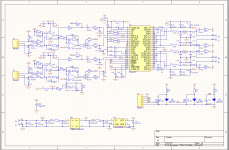
I hadn't looked at Class-D for a couple of decades and I was surprised at the performance levels now being achieved. This prompted me to have a go at building my own. After much reading I decided on the TPA3255 with post filter feedback in stereo BTL configuration.
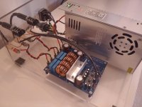
The power supply is a 400W 48V LED supply out of china turned down to 45V. I chose this one because it has a thermostatically controlled fan which doesn't kick in at normal listening levels. The minimal heatsink gets warm to the touch at ear shattering levels from my Klipsch floor standers.
I'm still looking for a suitable enclosure but in the meantime I've breadboarded it on some acrylic.
The inputs are balanced but my DAC isn't so I'm using balanced to unbalanced cables.
The chokes I wound myself using 15 turns of 2 x 1mm stands on sendust cores. with AL=51nH/T. These barely get warm.
I'm still waiting on some 48V to 15V DC-DC modules so in the mean time I've fitted a 7815 with a couple of 100R/1W droppers.
How does it sound? Well I don't have golden ears but it's on par with a tube hybrid that I have except that the bass seems tighter and it has a very neutral and uncoloured sound. Despite the single power supply, imaging is also very good. And it is so quiet.
Gerbers for the PCB are available if anybody wants them. How did I load this board? rather crudely! I apply solder to all the SMT pads using my iron and then dip each component in rework flux before reflowing them into place using a hot air tool.
Attachments
Wow! I want to try out this chip so bad!! A couple of years ago I started on a huge amp build for 2x tpa5630 cards only to find the sound quality lacking in those. So I never bothered to finish it. So now I am waiting for the 3255 to go mainstream, so I can finish my dream amp. I don't understand why this chip hasn't generated more of a buzz on this forum! Everyone that has built one says it sounds really good, and getting a usable 48V psu doesn't cost that much either. I've built and bought several tpa3116 amps but this is the next big thing!! Let'ss jump on the 3255 wagon instead ")
Yes, I am planning to do some THD measurements. My oscilloscope doesn't have the resolution needed but I will soon be getting a USB audio interface with the following spec for line input:
Dynamic Range 106 dB (A-weighted)
Frequency Response 20 Hz to 20 kHz, ±0.1 dB
THD+N <0.003% (minimum gain, -1dBFS input with 22 Hz/22 kHz bandpass filter)
Maximum Input Level+22 dBu
Gain Range 50 dB
Dynamic Range 106 dB (A-weighted)
Frequency Response 20 Hz to 20 kHz, ±0.1 dB
THD+N <0.003% (minimum gain, -1dBFS input with 22 Hz/22 kHz bandpass filter)
Maximum Input Level+22 dBu
Gain Range 50 dB
Nice work!
I also collected some experiences with TPA3255 in PFF configuration.
I posted my info here: http://www.diyaudio.com/forums/clas...th-x-amplifier-made-mobile-application-6.html
Now I wanted to ask you... Do you have problems with your PFF snubber (1uF + 3.0 Ohms) when there is no load connected?
In my design this snubber dissipates a lot of power and sometimes even dies if amp
clips without load. I need to replace the R then... But I'm actually using 1.33uF + 3.3 Ohms so corner frequency is a bit lower in my design.
Did you try this?
Thanks and regards
Bernhard
Nice work!
In my design this snubber dissipates a lot of power and sometimes even dies if amp
clips without load. I need to replace the R then... But I'm actually using 1.33uF + 3.3 Ohms so corner frequency is a bit lower in my design.
What do you expect, do a simulation and see for yourself. It's totally normal without any bw-limit on the inputs. With values from application note, the snubbers resonance frequency is at about 47kHz.
Been there, done that:
http://www.diyaudio.com/forums/clas...ng-them-everything-comes-182.html#post4987732
30A current in the snubber.
Last edited:
Perfect thanks.
With no load and with audio signal levels just below clipping there is no heating of the snubber resistors. I would suggest that there may be a HF instability in your design or that you are testing with unrealistic signal levels in the 10s of KHz region
With no load and with audio signal levels just below clipping there is no heating of the snubber resistors. I would suggest that there may be a HF instability in your design or that you are testing with unrealistic signal levels in the 10s of KHz region
Thanks for checking this in your design.
It only happens when the amp clips. Shortly before clipping it's all ok.
And no, my test signal was 1kHz sinus.
But actually I could solve this problem already by compensating the post filter feedback loop. It's stable now even with no load.
My phase shift is now between 15° and 45°.
I've used both linear and SMPS and I can't hear any difference except for fan noise in the SMPS
Could you link to the one you purchased? I'm interested in alternatives to the Meanwell which can be dearer in Australia.
Could you link to the one you purchased? I'm interested in alternatives to the Meanwell which can be dearer in Australia.
free shipping 360W 48V 7.5A Switching Power Supply Driver for CCTV camera LED Strip AC 100 240V Input to DC 48V output-in Switching Power Supply from Home Improvement on Aliexpress.com | Alibaba Group
Is the fan on that always on, or only at high power usage? I know the one on the meanwell is meant to only come on when it's hot.
I'm guessing it's probably a pretty noisy fan.
- Status
- This old topic is closed. If you want to reopen this topic, contact a moderator using the "Report Post" button.
- Home
- Amplifiers
- Class D
- My 1st Class-D Amp -TPA3255 with PFFB