You might have a look at...
LTC6902 Datasheet and Product Info | Analog Devices
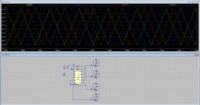
Resistor set 4 phase oscillator. It is in LTSpice under special functions. Other versions, two phase, 8 phase are available. Used for VRMs on motherboards.
I did test the chip, it give 90 degree triangles, usable but not for the 120 degree triangles, these need a processor.
Attachments
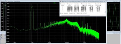
Yes 5 level, looks it suppress uneven harmonics as well, but think that this is not accurate answer of me.
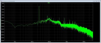
I have also 8 level see pic.
I have ordered LM319 has two comparators in one chip and is 80 nS speed.
with multilevel I can use smaller mosfets, current get divided over all mosfets, and voltage can be much lower, as result, low nC .
regards
use some newer better comparator
I did test the chip, it give 90 degree triangles, usable but not for the 120 degree triangles, these need a processor.
Why not using 90 degree ? More level better results
see datasheet, you can set this chip to be 120 degree?!!
Why not using 90 degree ? More level better results
see datasheet, you can set this chip to be 120 degree?!!
The amount of degree is not free to choose, it has impact on the switching pattern, the amount of levels etc, I use also differential input so it is better for feedback without a differential opamp, al do I doubt if a differential opamp between a dbtl and single input has much impact on distortion, think that we have very good opamps out there with very low distortions.
Hmm I have not read well then, the fase shift needs to be very precise, so can this chip do that with enough accuracy.
regards
Do somebody who has experience with class d design can tell me how to find the unity gain point for a sampled amplifier like class d, in the papers she talk about nyquist distance, likne D Nyquist:=3.25 for a natural sampled amplifier sampling theorem applies here, unity gain point fT = F switch : DNyquist, somebody knowledge of that? I havd done with ltspice until output singal was unity, but then things get strange, it did work I get with 5 level a unity gain around 250 Khz, switch frequency is 1 Mhz, triangles 90 degree each are 250 khz, multilevel do multiply carrier x 4, do I need the multplyed signal for the Nyquist calculation or the triangle carrier frequency? I think the sampling is also x 4 because the lowpass sees 1 Mhz.
This is needed for further calculations, who I am not good at, with simulation it is not clear what and where the point is, so maybe you guys can give some tips or documents about it.
regards
This is needed for further calculations, who I am not good at, with simulation it is not clear what and where the point is, so maybe you guys can give some tips or documents about it.
regards
Sure. Search for slope matching and average current mode control, don't focus on the word current. You should find some Unitrode, gobbled by Texas Instruments, application notes.
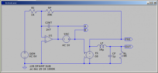
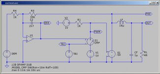
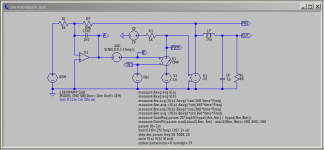
The following is not rigorous. However linear model attached. It assumes a supply voltage of +/-50V with a +/-1V triangle, 2V peak to peak, triangle wave using pre-filter feedback.
Pre-filter the signal is a rail to rail square wave. You have to convert it to a triangle wave for presentation to the PWM comparator. That makes your error amplifier a basic integrator.
If the slope of the feedback signal exceeds the slope of the triangle wave then, with a latched comparator, you would experience sub-harmonic oscillation. 'Naturally Sampled' the PWM signal would turn into fuzz.
TRI is 2V p-p @250KHz. That gives a dVr/dT of 2V/2u or 1E6V/S. You have to consider the current through RF for twice the supply voltage or 100V. Do something with dV/dT = i/CINT. It works out to be 2.56nF. I've used 2n7 as a standard value.
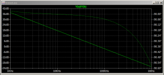
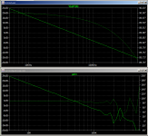
Loop Gain is measured by inserting an AC source in the Loop and plotting V(a)/V(b). Nominally crossover occurs at Fs/PI but the larger value for CINT knocks that down a little bit.
Next up a Switching Model.
The following is not rigorous. However linear model attached. It assumes a supply voltage of +/-50V with a +/-1V triangle, 2V peak to peak, triangle wave using pre-filter feedback.
Pre-filter the signal is a rail to rail square wave. You have to convert it to a triangle wave for presentation to the PWM comparator. That makes your error amplifier a basic integrator.
If the slope of the feedback signal exceeds the slope of the triangle wave then, with a latched comparator, you would experience sub-harmonic oscillation. 'Naturally Sampled' the PWM signal would turn into fuzz.
TRI is 2V p-p @250KHz. That gives a dVr/dT of 2V/2u or 1E6V/S. You have to consider the current through RF for twice the supply voltage or 100V. Do something with dV/dT = i/CINT. It works out to be 2.56nF. I've used 2n7 as a standard value.
Loop Gain is measured by inserting an AC source in the Loop and plotting V(a)/V(b). Nominally crossover occurs at Fs/PI but the larger value for CINT knocks that down a little bit.
Next up a Switching Model.
Attachments
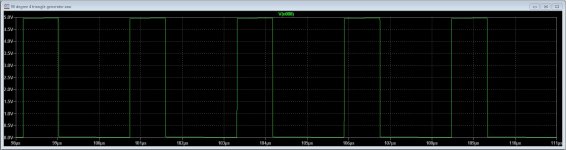
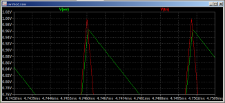
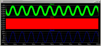
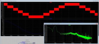
So... Here's the Switching Model. You will have to poke about to see some of the underneath bits. This is driven with a 1KHz 1V sine wave. Output post filter is 39V. Collecting V(tri) with V(err) you can see that the error slope does not exceed the triangle slope. Reduce the value of CINT and things will go Fuzz.
Attachments
Last edited:
As suggested this is not rigorous. If I tried I would embarrass myself. As a check...
LTspice: Extracting Switch Mode Power Supply Loop Gain in Simulation and Why You Usually Don't Need To | Analog Devices
or
LTspice: Basic Steps in Generating a Bode Plot of SMPS | Analog Devices
LTspice: Extracting Switch Mode Power Supply Loop Gain in Simulation and Why You Usually Don't Need To | Analog Devices
or
LTspice: Basic Steps in Generating a Bode Plot of SMPS | Analog Devices
Attachments
Thanks for respons.
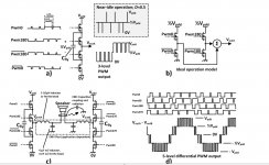
I need the solution for a 5 level pwm apmplifier, and I test a 8 level one, it has 4 triangles 90 degree shift, 8 level has 45 degree shift, as I did read unity gain is where signal is equal the input as that is the case by unity.
for clarity it is a natural sampled version with 5 levels, I have a controller who can give postfeedback. I have to find the unity point in open loop. it can be calculated with nyquist but with a 5 level do I use the carrier frequency or the multiplicated frequency (x4 = 1 Mhz) switching looks more difficult to calculate then analog..
regards
Attachments
Gosh sorry about that. I was just giving you a method and the reasoning behind it. Otherwise, assuming you were not expecting someone else to do the work for you, it looks like you know the answer already. The unity gain is unity at unity and the post feedback controller is set equal to the nyquist using a frequency. Thanks for the added clarity.
Gosh sorry about that. I was just giving you a method and the reasoning behind it. Otherwise, assuming you were not expecting someone else to do the work for you, it looks like you know the answer already. The unity gain is unity at unity and the post feedback controller is set equal to the nyquist using a frequency. Thanks for the added clarity.
All help is welcome afcourse, appreciate waht you do to help, and I read a lot on the internet, I have papers printed where formulas are, I see you have extensive knowledge of LTspice I have not that much, what I did is get input frrequency as high until it gets 1 x but offset do go change to negative when this input frequency gets above 150 Khz.
here is the link with the formulas about the feedback I did want to use. some kind of PID controller, it seems that no using a integrator give better sound quality also.
https://www.meng-engineering.ch/_do...er-Feedback-Halfbridge-Single-Supply-170V.pdf
thanks.
You are just discovering the pitfalls/deceptions implicit in some modulator schemes commonly in use.
- The paper advertising a company calling "class-BD" to "2-phase". Incidentally during last 10 years the aforementioned company lost most of its professional customers and was rescued by residential business. Now China is making a lot of pro-audio.
- The fact that these modulators (BD, phase shift) are almost unable to damp common-mode oscillation. You may get less ringing by adjusting some initial inductor currents and capacitor voltages, or coding a pair of simulated damping resistors to ground whose value increases with time. In general two class AD outputs are needed for a BTL capable of damping common-mode interference as well as differential-mode.
You are also getting closer to the design path I followed. Before investigating phase-shift self-oscillation in detail (10yr ago) I was doing triangle modulation with mixed voltage and current feedback, getting good results. I developed a sinewave inverter prototype that at low current used simple MCU-driven class BD modulation for low idle consumption, and at high current used analog triangle modulator with voltage/current feedback for removing output filter (LCLC) resonance. The design ended up being used as a low-impedance low-distortion AC generator for calibrating AC power meters.
This is a time ago @Eva I have in the meantime did some more stuff, like multilevel systems. What concerns common mode problems who I did tackle with common mode coils who did cancel that, I had no common mode with 5 level versions of Class D, what was of concern, I need triangles, self osc do not work, and also when do post feedback, the fase get ruined and the multilevel action disturbing, so I have no multiplying effect but some extra carriers who do extend radiation to higher levels.
regards
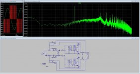
I share my H8 simulation.
Still don't have feedback, but you can add by yourself.
Thanks for sharing, have you also the ti_models.lib?
thanks.
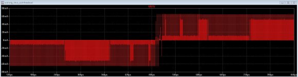
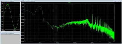
This one a three level I have done so that with a fase shift I get around zero voltage output pulses to prevent crossover, it does work and has very low distortion, not much difference with high or low output power or frequency. This one does very well, UCD with post and prefeedback. with fase shift. Witl lagre deadtimes I get -80 dB distortion figures.
Attachments
- Status
- This old topic is closed. If you want to reopen this topic, contact a moderator using the "Report Post" button.
- Home
- Amplifiers
- Class D
- Class D investigation.