Yehh that is quite incredible amplifier, but this demands I think a quite extensive lab to design and special to fabricate.
It is a full tube headphone amp, $55.000 is also quite a amound of mony, as mine will stick so around some $4.000 for stereo.
it is beautifull designed, I agree.
This also is also very nice build.
YouTube
regards
It is a full tube headphone amp, $55.000 is also quite a amound of mony, as mine will stick so around some $4.000 for stereo.
it is beautifull designed, I agree.
This also is also very nice build.
YouTube
regards
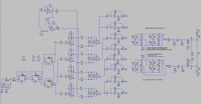
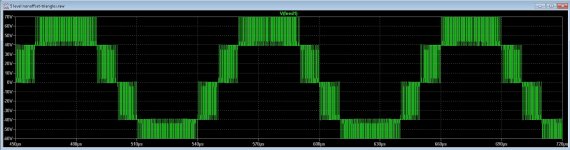
5 level this time fase shifted version, it do quadruple the carrier to 1.6 Mhz without stressing the switches who do work on 400 Khz so I can get quite low making good switch results. Also the voltages on switches are halved, and I just needs two single floating supplies. If this 5 level swither is usable for audio, I do not now, it is used for inverters, quite nice tough, making a sinusoidal output with high efficienty.
the HD is -60dB openloop on 4 ohm with 3600 watts of power. Common mode suppression is quite good, I have low pass setting on 100 Khz. EMI is also much lower then with normal class D technology.
However the parts count is some bigger, the need for 8 switching mosfets and 4 IR2010 chips, also I do not now if the charge pump do work with 5 level for the high side mosfets, then I need a extra supply line 15 volts higher then supply, but if i get a very nice amp, why not, mony is not real issue, high end is.
quite impressive, but yehh it is only simulation, however the working of the system is what counts and learn me some about this.
regards
Hmm, yes in simulation is impressive, but I wonder how it sounds.
There are galvanically isolated mosfet drivers (new technology IC not too expensive). You just use separate power supply instead of bootstrap. (for driving)
How you managed to produce 5 triangles all level shifted exactly ?
Hmm, yes in simulation is impressive, but I wonder how it sounds.
There are galvanically isolated mosfet drivers (new technology IC not too expensive). You just use separate power supply instead of bootstrap. (for driving)
How you managed to produce 5 triangles all level shifted exactly ?
Hi Grizlek
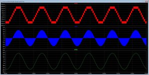
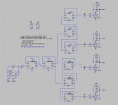
I have two kinds of setups, leveled triangles, four above each other and the fase shifted versions.
The fase shift I did with flip flops and a clock signal.
However only the carrier multiplication is interesting, for normal home use and 500 watts, just a 3 level will do, but then I have only doubling the carrier.
Biggest problem with 3 or 5 level is crossover distortion, for 5 level there are two extra crossover points, for 3 level it is less complicated to cure that with offset into the comparators.
However, now the new kind of mosfets are coming, like the Gan fets, the need for multilevel for class d is not so important anymore, however the carrier doubling stays interesting for copy with EMI.
For as the insolated driver, I do not now if a opto coupler is a ideal choise to use in this, but is needed, I can also use a other kind of output capacitor coupled who need not this.
Last picture is the hybrid.
Attachments
Last edited:
Hi Grizlek
I have two kinds of setups, leveled triangles, four above each other and the fase shifted versions.
The fase shift I did with flip flops and a clock signal.
However only the carrier multiplication is interesting, for normal home use and 500 watts, just a 3 level will do, but then I have only doubling the carrier.
Biggest problem with 3 or 5 level is crossover distortion, for 5 level there are two extra crossover points, for 3 level it is less complicated to cure that with offset into the comparators.
However, now the new kind of mosfets are coming, like the Gan fets, the need for multilevel for class d is not so important anymore, however the carrier doubling stays interesting for copy with EMI.
For as the insolated driver, I do not now if a opto coupler is a ideal choise to use in this, but is needed, I can also use a other kind of output capacitor coupled who need not this.
Last picture is the hybrid.
If you have "X" dead time in half bridge version , like 50 nS, no feedback and X number of THD. In 5 level D class with 50 nS dead time, you will have approximately X/5 THD level. Proven by Matlab or LT spice with ideal elements.
This is not opto coupler this is inductive coupling in single soic IC,.. very fast, ot incorpoarate rising edge delay matching, and you can tune dead time from 10 nS to higher values.
This is new technology , google UCC21520 year 2017 datasheet.
Can you explain more this hybrid, (last picture, why it works and sounds so good). This is your desing ? can you send LT spice file so I can simulate and see how it works (if project is "open source" of course). Whats the purpose of op amp ..What about THD, impulse response and other relevant LTspice results? Also how it behaves regarding clipping and THD, like TUBE amp or like transistor AMP.
Also could vertical mosfets be used for output stages, this lateral audio mosfets is very hard to buy there days (harder then tubes), also maybe SiC mosfets can be used, they have low gate capacity, but ...
Last edited:
If you have "X" dead time in half bridge version , like 50 nS, no feedback and X number of THD. In 5 level D class with 50 nS dead time, you will have approximately X/5 THD level. Proven by Matlab or LT spice with ideal elements.
This is not opto coupler this is inductive coupling in single soic IC,.. very fast, ot incorpoarate rising edge delay matching, and you can tune dead time from 10 nS to higher values.
This is new technology , google UCC21520 year 2017 datasheet.
Can you explain more this hybrid, (last picture, why it works and sounds so good). This is your desing ? can you send LT spice file so I can simulate and see how it works (if project is "open source" of course). Whats the purpose of op amp ..What about THD, impulse response and other relevant LTspice results? Also how it behaves regarding clipping and THD, like TUBE amp or like transistor AMP.
Also could vertical mosfets be used for output stages, this lateral audio mosfets is very hard to buy there days (harder then tubes), also maybe SiC mosfets can be used, they have low gate capacity, but ...
Hi
The hybrid is not yet open source, because it go to be a selling amp.
I have designed it, and it do well in real time, already tested, the HD is -60 dB and have nice ear loving harmonics, it is open loop. I have a vertical version who has a beefy driver extra and a runaway correction but need to test it, never did.
The opamp is a dc servo, this is needed because tubes are bad in stability and it drives the mosfet in dc mode, no caps.
Yes I now about the sic, maybe a hybrid circlotron.
regards
Attachments
Last edited:
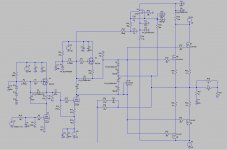
Forget the previous post, I did a UCD with a combination of integrator-PI and get a very low distortion, it seems to do wel in simulation, even with big dead times, I have used pre-post feedback.
It has low pass inputs keeping carrier out and it is a Fase shifted version with sync, doubling the carrier.
Also stable with clipping high bandwidth.
It has low pass inputs keeping carrier out and it is a Fase shifted version with sync, doubling the carrier.
Also stable with clipping high bandwidth.
Attachments
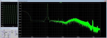
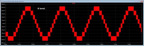
I have now I am waiting for parts, dis some sims with 5 and 8 level switching stuff.
The found stuff about the postfeedback with formulas do quite nice, I have use a 8 level, x 8 carrier is 2 Mhz and 100 Khz -3 low pass, maybe I can even go higher.
I do not now however how the switches go behave, because of the 8 levels, do go this into problems with audio, normally with a inverter for only 50 hz that is quite more relaxed then.
However I get with deadtime (if this is needed there?) quite low distortions, also on 20 Khz.
regards
Attachments
I have now I am waiting for parts, dis some sims with 5 and 8 level switching stuff.
The found stuff about the postfeedback with formulas do quite nice, I have use a 8 level, x 8 carrier is 2 Mhz and 100 Khz -3 low pass, maybe I can even go higher.
I do not now however how the switches go behave, because of the 8 levels, do go this into problems with audio, normally with a inverter for only 50 hz that is quite more relaxed then.
However I get with deadtime (if this is needed there?) quite low distortions, also on 20 Khz.
regards
May we see the schematics of this 8 level ? Signals do look very nice
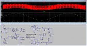
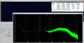
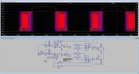
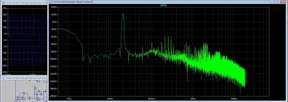
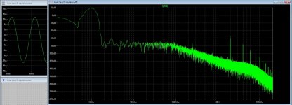
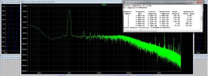
Grizlek here are the 5 level class D and the open loop distortion, it is sim so in real live things get much worse, or I am lucky if not.
have include also a twree level self oscillating version, just build it, I like to see how it works in real live.
The 5 level has postfeedback however making the feedback filter oke, it needs calculation, carrier is x 4, so 250 Khz get 1 Mhz, can use smaller mosfets power gets evenly divided over mosfets..
Lib's are to big for put here, search on internet for them. or go here
For LTspice users. Libraries of models, examples, etc
regarts.
Attachments
Last edited:
Grizlek here are the 5 level class D and the open loop distortion, it is sim so in real live things get much worse, or I am lucky if not.
have include also a twree level self oscillating version, just build it, I like to see how it works in real live.
The 5 level has postfeedback however making the feedback filter oke, it needs calculation, carrier is x 4, so 250 Khz get 1 Mhz, can use smaller mosfets power gets evenly divided over mosfets..
Lib's are to big for put here, search on internet for them. or go here
For LTspice users. Libraries of models, examples, etc
regarts.
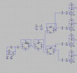
How would you in real life make phase shifted triangles? And THD will be affected if that phase shift is good?
How would you in real life make phase shifted triangles? And THD will be affected if that phase shift is good?
Maybe like this? or use a chip and program it in it, there are a lot of nice cpu's like a FPGA chip.
You can go read over multilevel inverters on google a lot of info there.
I think more then 5 level for audio is because of parts count maybe not such idea, but you can set frequency to 150 khz and get on output 1.2Mhz making even output low pas higher and get 150 Khz bandwidth amp, but it is complicated for postfeedback.
Oke I get the parts for the circlotron so get to work after weeks of waiting because of other work and friend who did contract cancer and needs help, she did survive and is in remission.
regards
Attachments
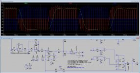
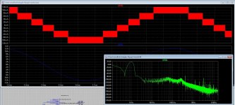
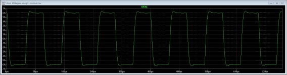
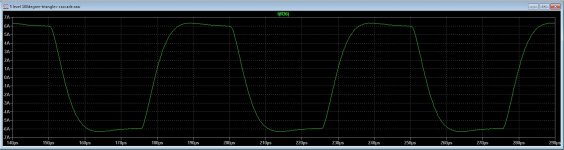
While the paint does dry on the wall I have play some with levels and faseshifts, the way I did now give a very nice open loop respons, I need however a cheap but very fast comparators, do you now what to use, I have the lT1016 here but are single ones, maybe better for test pcb making also.
Square tests are one 10 Khz and one 20 Khz.
regards
Square tests are one 10 Khz and one 20 Khz.
regards
Attachments
Last edited:
While the paint does dry on the wall I have play some with levels and faseshifts, the way I did now give a very nice open loop respons, I need however a cheap but very fast comparators, do you now what to use, I have the lT1016 here but are single ones, maybe better for test pcb making also.
Square tests are one 10 Khz and one 20 Khz.
regards
5 level ?
You might have a look at...
LTC6902 Datasheet and Product Info | Analog Devices
Resistor set 4 phase oscillator. It is in LTSpice under special functions. Other versions, two phase, 8 phase are available. Used for VRMs on motherboards.
LTC6902 Datasheet and Product Info | Analog Devices
Resistor set 4 phase oscillator. It is in LTSpice under special functions. Other versions, two phase, 8 phase are available. Used for VRMs on motherboards.
It produces square.... then integrator..You might have a look at...
LTC6902 Datasheet and Product Info | Analog Devices
Resistor set 4 phase oscillator. It is in LTSpice under special functions. Other versions, two phase, 8 phase are available. Used for VRMs on motherboards.
You might have a look at...
LTC6902 Datasheet and Product Info | Analog Devices
Resistor set 4 phase oscillator. It is in LTSpice under special functions. Other versions, two phase, 8 phase are available. Used for VRMs on motherboards.
Thanks for the tip.
5 level ?
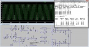
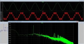
Yes 5 level, looks it suppress uneven harmonics as well, but think that this is not accurate answer of me.
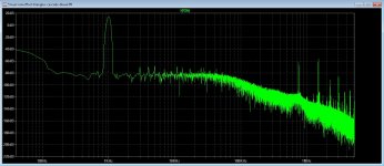
I have also 8 level see pic.
I have ordered LM319 has two comparators in one chip and is 80 nS speed.
with multilevel I can use smaller mosfets, current get divided over all mosfets, and voltage can be much lower, as result, low nC .
regards
Attachments
Last edited:
- Status
- This old topic is closed. If you want to reopen this topic, contact a moderator using the "Report Post" button.
- Home
- Amplifiers
- Class D
- Class D investigation.