Thank you Pafi for your responds.
I do not need much help and you have more things to do then help me, I am already thankfull to give me some hints about the D amps, she can be very complicated.
I do find 105 102 nS for the powercomparor quite fast, as say someone that it is old, the most amplifier designs are old, even D come from 1952.
Oke, Last quenstion R22 and 24 from what schematic?
The original, in the article you linked. Your schematic is unreadable for that part.
I did not read it because I have not seen it, that is why I have this tread, so things get not everywhere .
Sorry, I answered there to your question:
http://www.diyaudio.com/forums/clas...00-watts-using-2-mosfets-432.html#post4939403
As for the Tas power modules these are noce but I like the challence of discrete stuff, and special try to lower distortions, so I di read a lot.. for discrete power modules I do set dead time with the gate resistors, this works fine and is simple.
Maybe this gate driver is better, because of higher voltages., IR2011S
regards
If you need high power, yes. But for high quality...
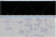
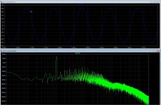
If I look to the simulations it looks like getting low distortion is not that difficult, -80dB 20 Khz and 80 volts Peak is not bad in 8 ohms, it looks like class D do keep it quite low over the whole bandwidth of the amp, in my case to 50Khz.
Multi pole fase shift do quite well, just one opamp and a power comparator do work, maybe a chip comparator who is faster can do even better but needs then a very fast power section, and power mosfets are not that fast because of gate capacity and needs a beefy driver to switch properly. however the power comparator do nice even above 1 Mhz, I use 800 Khz, I need bandwidth..
regards
Attachments
Did you try what it does without load and for example with 1 kHz squarewave input?
Njet
I do try keep in mind that a modulated carrier do NOT like squares because of harmonic intent, it is not a good
way of testing a D amp, only liniair amps can give info with it like ringing and such.
But I try what happens.
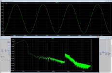
Hmm without load it do fine, very stable on carrier 800 Khz without load, however when I shut off audio it do not switch anymore
this it did also with load, putting just 0.001 volts it start again and is stable maybe it needs offset because I use the opa365
on 2 x 2.5 volts, this chip is max 5 volts single with ref..
Last edited:
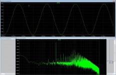
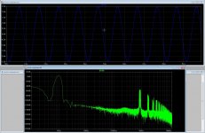
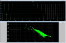
After calculate the coil the right way I get now tests with and without load incl a square wave (with and without load.)
Also the switching carrier to see it looks quite good, low distortion maybe because of multipole fase shift oscillator, it drops also less when near the rails.
regards
Also the switching carrier to see it looks quite good, low distortion maybe because of multipole fase shift oscillator, it drops also less when near the rails.
regards
Attachments
-
 ScreenHunter_ Jan. 09 15.58.jpg315.9 KB · Views: 76
 -
 ScreenHunter_ Jan. 09 15.38.jpg258.9 KB · Views: 85
 -
 ScreenHunter_ Jan. 09 15.37.jpg232.5 KB · Views: 82
 -
 ScreenHunter_ Jan. 09 15.33.jpg239.9 KB · Views: 88
 -
 ScreenHunter_ Jan. 09 15.29.jpg256.6 KB · Views: 289
 -
 ScreenHunter_ Jan. 09 15.28.jpg234.6 KB · Views: 303
Last edited:
Njet
I do try keep in mind that a modulated carrier do NOT like squares because of harmonic intent, it is not a good
way of testing a D amp,
The reason why square wave IS a good stimulation for testing is that it contains harmonics, this way you can check effectively at many frequencies at the same time.
(Not intent but content.)
only liniair amps can give info with it like ringing and such.
Ringing and such can happen to any network, not only linear. I already shown this in the other thread.
Spelling: L-I-N-E-A-R! Please!
But I try what happens.
Hmm without load it do fine, very stable on carrier 800 Khz without load, however when I shut off audio it do not switch anymore
this it did also with load, putting just 0.001 volts it start again and is stable maybe it needs offset because I use the opa365
on 2 x 2.5 volts, this chip is max 5 volts single with ref..
This can be the result of bad simulation setting also.
Doesn't switch? OK, but what it does?
The reason why square wave IS a good stimulation for testing is that it contains harmonics, this way you can check effectively at many frequencies at the same time.
(Not intent but content.)
Ringing and such can happen to any network, not only linear. I already shown this in the other thread.
Spelling: L-I-N-E-A-R! Please!
This can be the result of bad simulation setting also.
Doesn't switch? OK, but what it does?
What it does is just test it in real world, for the simulations, the settings are just reason that it did not right, special switching stuff is difficult to simulate, maybe Tina is better in it.
Yes I now I write everytime liniair, but must be lineair, but I am somebody who do not care much on spelling trouble.
Last picture you see what happens as someting is not set right in simulation, for special when get it faster, digital sims are slow, that is real world..
see some how low distortion it has, with extra poles in signal path as article did say, there is sooo much possible on the D amp technology, even coil less.
Ohh yes I say about the square that it in a coil do behave bad, I do most test 1 khz 10 kz 20 khz and see, a square is good for get lowest ringing and such, and yes in a amp it can also be, like in my circlotron design who go start again as parts arrive, but do not have them yet, so i play some with D amps, my friend the High End tube lover says class D do switch, that do never sound right, but now I get the drive to let him listen some day, maye I also do not like them, the circlotron allfet do sound very sweet and fast.
regards
Attachments
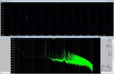
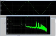
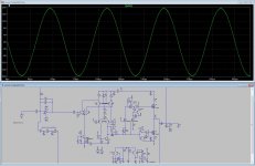
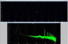
Why the low pass filter of the amp has to be butterworth? I did try a bessel 24 dB lowpass who is fase correct and get this on almost rail to rail output of the amp, 90 volts peak and get -70 dB harmonic distortions. I did take the feedback from the first core, and the last is extra section because bessel is less deep.
http://www.embedded.com/print/4321635
http://www.embedded.com/print/4321635
Attachments
Last edited:
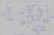
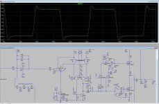
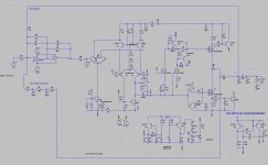
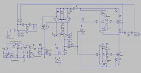
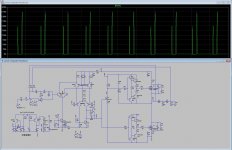
Can somebody look at the power comparator, I have use a beefy driver for fast switching, but did I do right, so that is why I ask.
I have quite low distortion with these drivers, because square is better of quality and I do use a bessel lowpass
because these filters has fase liniair behavior so lower HD..
thanks.
I have quite low distortion with these drivers, because square is better of quality and I do use a bessel lowpass
because these filters has fase liniair behavior so lower HD..
thanks.
Attachments

Did you check it for cross-conduction?
What is the square look like?
Hi Pafi
The crossconduction I did not measure, but it has death time throught gate resistors.
I use high switch frequenty so that is why I did use a beefy driver in super follower configuration to get very low impedance on gate drive output, I did have this from a schematic so it is not mine.
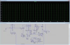
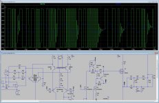
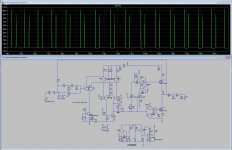
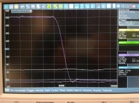
this is the square, 900 Khz idle.. (this can be lower) I have a 24dB bessel on end, seems a bessel is faselineair..
Attachments
Measure cross-conductance! It tooks 5 sec for you.
If you are so sure it is good that you don't have to check, then why asking us?
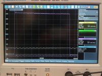
I wouldn't say this square was really "good quality", nor fast, but at least the horizontal resolution is not enough to clearly see deatails. Although a sing of cross-conduction is still visible.
Does beefy mean big size? Then it is beefy indeed.
If you are so sure it is good that you don't have to check, then why asking us?
I wouldn't say this square was really "good quality", nor fast, but at least the horizontal resolution is not enough to clearly see deatails. Although a sing of cross-conduction is still visible.
Does beefy mean big size? Then it is beefy indeed.
Measure cross-conductance! It tooks 5 sec for you.
If you are so sure it is good that you don't have to check, then why asking us?
I wouldn't say this square was really "good quality", nor fast, but at least the horizontal resolution is not enough to clearly see deatails. Although a sing of cross-conduction is still visible.
Does beefy mean big size? Then it is beefy indeed.
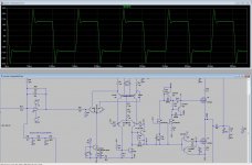
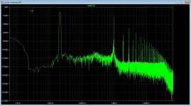
Problem is I do not know ltspice so well, if you can explane me how to do, I can measure current resistor on drain, then i get 150 amps spikes, and one 12 amps spike.
I am not so shure, so I did ask, I am more learning from it then build it, first the circlotron has to be ready however still waiting on last parts.
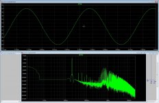
I can reach -100dB distortion with it, I think the original powercomparator is the best one, because that one do be fast, and can even do 800 Khz carrier,
regards
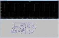
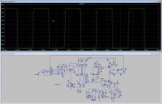
here some more also the current and the distortions on 10 volts and higher using more poles in low pass do handle HD nicely but needs experimenting..
The first picture has the most nice square, but I think about build it some day because simulations are not always accurate, special with switching technology..
High current peaks can also be the body diode of the mosfets, or capacitances.
regards
The first picture has the most nice square, but I think about build it some day because simulations are not always accurate, special with switching technology..
High current peaks can also be the body diode of the mosfets, or capacitances.
regards
Attachments
-
 ScreenHunter_ Jan. 18 15.38.jpg324.6 KB · Views: 54
 -
 ScreenHunter_ Jan. 19 18.28.jpg316.1 KB · Views: 67
 -
 ScreenHunter_ Jan. 19 20.48.jpg235.4 KB · Views: 84
 -
 ScreenHunter_ Jan. 19 20.50.jpg238.8 KB · Views: 70
 -
 ScreenHunter_ Jan. 19 20.32.jpg207 KB · Views: 81
 -
 ScreenHunter_ Jan. 19 19.35.jpg228.2 KB · Views: 95
Last edited:
This is the beauty of simulator: everything can be measured.
These spikes are clearly from the cross-conduction.
Capacitive spikes are much shorter, diode recovery happens only on one edge, leading or trailing depending on output current polarity (and nothing at small output current).
When somebody actually builds ClassD amp this is usually the first experience. Heat, crash, bang, smoke... but as long as it works it has beautiful voice.
The task is not to achieve extraordinarily low distortion regardless of everything else. The task is to do everything acceptable. I wrote a list in the other topic.
And I wrote this to you in this topic:
So more attention please!
Simulators are very powerful tools. They work very well, if you
- insert realistic parts (with parasitics - inductance!)
- watch the important signals
- set analysis parameters well (this is mostly done well by default, but not always)
If you don't want to deal with cross-conduction and dead time, and want to concentrate only on the filter and feedback, then better to use an ideal power comparator. And then you can separately design a good power comparator, tested in open loop to really know what it is capable for. Then join these two!
These spikes are clearly from the cross-conduction.
Capacitive spikes are much shorter, diode recovery happens only on one edge, leading or trailing depending on output current polarity (and nothing at small output current).
When somebody actually builds ClassD amp this is usually the first experience. Heat, crash, bang, smoke... but as long as it works it has beautiful voice.
The task is not to achieve extraordinarily low distortion regardless of everything else. The task is to do everything acceptable. I wrote a list in the other topic.
And I wrote this to you in this topic:
When simulating, don't focus only 1 parameter! switching freq and distorition is 1 thing, but always check if it really work in switch mode, and doesn't make cross conduction!
So more attention please!
Simulators are very powerful tools. They work very well, if you
- insert realistic parts (with parasitics - inductance!)
- watch the important signals
- set analysis parameters well (this is mostly done well by default, but not always)
If you don't want to deal with cross-conduction and dead time, and want to concentrate only on the filter and feedback, then better to use an ideal power comparator. And then you can separately design a good power comparator, tested in open loop to really know what it is capable for. Then join these two!
Thanks Pafi for the help, I do now that for simulation there is a need for good models and including of pcb induction and parasitics, however it is always a need to build and test, with modern parts this is quite easy to get good goals.
The power comparator I do use in simulation is the version from the article I have send already, it uses rf parts for fast transitions, the death time is adjusted with gate resistors.
For the bang and bang, I use always a laboratorium supply, who do switch of when things go wrong, it have help me a lot in past to prevent costs for blown parts.
But I go use your advise, I am not complete oke with ltspice, however I have also multisim who is more easy but as demo so not such big schematics.
For as the article did say about death time, changing the resistors did not do much in simulation, you did mention a while back that the 200 ohm resistor has to be swapped.
The power comparator has very fast rise and fall times.
regards
Attachments
- Status
- This old topic is closed. If you want to reopen this topic, contact a moderator using the "Report Post" button.
- Home
- Amplifiers
- Class D
- Class D investigation.