Hi All
First I wish the people here a happy and audiophile 2017.
I did post some on thread's but better is my own one.
I have a thread here also with a allfet circlotron however I wait for parts and so I have to do something els to eat my time on the end of the lazy year.
I thought I do test some digital amps, or better class D switching amps, as I did read everywhere the HD of them but also the kind of sound quality is wide spread as from hars to warm, and even a single ended tube warm sound.
The technology behind this amps is very wide, sigma delta where some 001 is fill in with 011 fo get lower switching and self oscillating UCD, the last I did some reading on, with multipole HD shaping we can get very low HD.
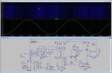
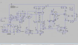
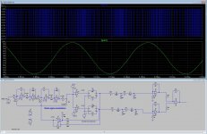
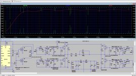
see some excamples, I have sims discrete power comparator in picture 3 and 4 the first are just a complemmentairy stage after a comparator chip, the chips used are very fast..
To get good sound the choose of opamp is important, that is why I use burr brown opa 2365 or single one opa365 who is allfet but nog yet do I now how it sounds, this is later care..
regards
First I wish the people here a happy and audiophile 2017.
I did post some on thread's but better is my own one.
I have a thread here also with a allfet circlotron however I wait for parts and so I have to do something els to eat my time on the end of the lazy year.
I thought I do test some digital amps, or better class D switching amps, as I did read everywhere the HD of them but also the kind of sound quality is wide spread as from hars to warm, and even a single ended tube warm sound.
The technology behind this amps is very wide, sigma delta where some 001 is fill in with 011 fo get lower switching and self oscillating UCD, the last I did some reading on, with multipole HD shaping we can get very low HD.
see some excamples, I have sims discrete power comparator in picture 3 and 4 the first are just a complemmentairy stage after a comparator chip, the chips used are very fast..
To get good sound the choose of opamp is important, that is why I use burr brown opa 2365 or single one opa365 who is allfet but nog yet do I now how it sounds, this is later care..
regards
Attachments

Faster distortion simulation:
- Simulate only 2 periods! (I usually use 1 kHz, 2 ms.)
- Set "Time to start saving data" to the start of 2nd period (1 ms)!
- FFT can "Use Extent of Simulation Data".
- Don't use any windowing function!
Above is for fast but still accurate analysys. But if there is some weird aperiodical (transient) behaviour, or signal freq is not exactly known, then you may have to use multiple periods (even if not exactly whole periods) and to smooth the fractional period by windowing. For exact amplitude reading flat-top windowing is the best, but it may hide some fine details. Generally Blackmann-harris is good. But use windowing only if many periods of the interesting freq is available for analysis!
Attachments
Last edited:
Hi Pafi
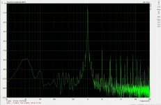
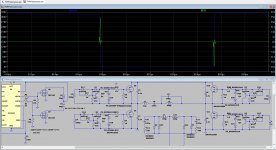
Thanks for the info, I have did some tests to see what happens, see the pictures.
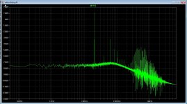
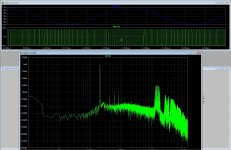
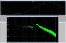
TNT you did ask Pafi? because I did not see these peaks on sim, but did use a HD shaper as was on papers, did try some different things to learn and see, class D is not such playtool als liniair amps, she are quite complicated, also in pcb design.
See on plot that the carrier is on 1.5 Mhz, but when I come close to rails it drops to 700 khz. this is to high and bad for EMI.
regards
Thanks for the info, I have did some tests to see what happens, see the pictures.
TNT you did ask Pafi? because I did not see these peaks on sim, but did use a HD shaper as was on papers, did try some different things to learn and see, class D is not such playtool als liniair amps, she are quite complicated, also in pcb design.
See on plot that the carrier is on 1.5 Mhz, but when I come close to rails it drops to 700 khz. this is to high and bad for EMI.
regards
Attachments
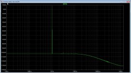
Do you have some insight in why almost all Class D amps has a distorsion peak at around 4-5k and then to drop to lower values again at say 10khz?
//
Switching over filters in the AP.
Do you have some insight in why almost all Class D amps has a distorsion peak at around 4-5k and then to drop to lower values again at say 10khz?
//
It drops because measured through a very sharp 20 kHz low pass filter what filters out 3rd harmonic as soon as signal freq exceeds 6.6 kHz. (Or simply FFT components above 20 kHz are ignored.) The increasing part is due to decreasing loop gain. Measured the same way all amps behave this way, not only ClassD, but this strict bandwidth limit is not always applied to linear amps.
Hi Pafi
Thanks for the info, I have did some tests to see what happens, see the pictures.
See on plot that the carrier is on 1.5 Mhz, but when I come close to rails it drops to 700 khz. this is to high and bad for EMI.
regards
I don't know what you changed and what do you expect.
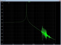
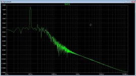
I did sim with your setup Pafi
see the result, is this what you mention.
regards
No, I explicitely wrote NOT to use windowing on single period. I wrote this 2 times.
I don't know what you changed and what do you expect.
I did change the feedback parts, so oscillation did change, now it was very high, this way I do learn some things what happens, that is the fun of simulation. some papers has very nice tests, but I get negative offset in the discrete comparator.
Do you now a very fast output stage? for example with ic comparator and ic gate drivers, there are gate drivers who go quite high I did want to test on 800 Khz carrier. Did ask also if soft switch is possible, but I think this do not is the case because we have to demodulate audio and with extra coils this go wrong.
The use of a triangle wave is the old system, it let stay the carrier frequentie stable, when use a very high quality triangle and analog feedback this can give a nice stable amp, the self oscillating versions did have the problem with the lowering carrier when output get higher and drops when get near supply rails, here can a transistor, two resistors on both sides make a nice protection, shut of the amp when current peaks, with a hold for 30 seconds before the amp switch on again this kind of electronics is not that difficult.
I have a clip detector who shut of the amp for 1 minute (it is tube hybrid) and yjis works nicely.
For ltspice, I have design the allfet circlotron but when I measure in real time I get quite high harmonics, when simulation I get verly low distortions, possible because I did measure with the pc and the floating circlotron output things get messed up, I do need to build a differential to single output converter, then I can do it better, agree?,. But Maybe I did sim wrong, but measuring just one half of the amp is also not a real nice way, so I go build a converter or maybe one on ebay.
regards
Attachments
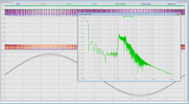
This delta sigma one is also a lot on the internet, however the high pulse rate is a problem, we need more 0001 to set 0011 or even 0111 to get lower rate with wider pulses, maybbe feed in in a pwm who make pulses wider etc etc, complicated stuff.
nice stuf there is going on.
But I have the circlotron parts so I go make it on a new PCB, the D I do keep watching and I play with it in spare time.
regards
nice stuf there is going on.
But I have the circlotron parts so I go make it on a new PCB, the D I do keep watching and I play with it in spare time.
regards
Attachments
I did change the feedback parts, so oscillation did change, now it was very high, this way I do learn some things what happens, that is the fun of simulation. some papers has very nice tests, but I get negative offset in the discrete comparator.
Do you now a very fast output stage?
TAS... power stages. 50 ns delay, negligible dead time. There are many fast comparators.
Fast gate driver: UCC27200 and similar.
For ltspice, I have design the allfet circlotron but when I measure in real time I get quite high harmonics, when simulation I get verly low distortions, possible because I did measure with the pc and the floating circlotron output things get messed up, I do need to build a differential to single output converter, then I can do it better, agree?
Yes, certainly a differential measurement amp is needed.
,. But Maybe I did sim wrong, ...
This is also a possibility. Many things can go wrong.
When simulating, don't focus only 1 parameter! switching freq and distorition is 1 thing, but always check if it really work in switch mode, and doesn't make cross conduction! I think this is not the situation here. I asked you to change R22 and 24, but no response.
I can't help you in switching freq. This feedback is too complicated to analyse in head, and I don't have the simulation file and no time to play with it.
Chocoholic made very through research, worth to read his posts. The others in ex-UcD 1200W topic don't understand anything from electronics.
Thank you Pafi for your responds.
I do not need much help and you have more things to do then help me, I am already thankfull to give me some hints about the D amps, she can be very complicated.
I do find 105 102 nS for the powercomparor quite fast, as say someone that it is old, the most amplifier designs are old, even D come from 1952.
Oke, Last quenstion R22 and 24 from what schematic? I did not read it because I have not seen it, that is why I have this tread, so things get not everywhere .
As for the Tas power modules these are noce but I like the challence of discrete stuff, and special try to lower distortions, so I di read a lot.. for discrete power modules I do set dead time with the gate resistors, this works fine and is simple.
Maybe this gate driver is better, because of higher voltages., IR2011S
regards
Last edited:
One to try
OPAMP ---> LT1671---
---> NC7SZ08 ---> HI --> DRIVER
&
---> NC7SZ02 ---> LO -------^
Just before the output inductor feed back to the opamp in front of the LT1671.
http://cds.linear.com/docs/en/datasheet/1671fs.pdf
OPAMP ---> LT1671---
---> NC7SZ08 ---> HI --> DRIVER
&
---> NC7SZ02 ---> LO -------^
Just before the output inductor feed back to the opamp in front of the LT1671.
http://cds.linear.com/docs/en/datasheet/1671fs.pdf
Last edited:
One to try
OPAMP ---> LT1671---
---> NC7SZ08 ---> HI --> DRIVER
&
---> NC7SZ02 ---> LO -------^
Just before the output inductor feed back to the opamp in front of the LT1671.
http://cds.linear.com/docs/en/datasheet/1671fs.pdf
Thanks mate
I have test with a comparator who is 2.9 nS but has max 5 volts supply, reason for such fast one was the triangle generation together with a fery fast opamp, for sound integrator I did use the opa365, I have this from a datasheet and distortion with it can be 0.009 while goal was 0.1, without feedback, with feedback we get pretty low distortion.
I did read balanced output did cancel also some distortion special even ones.
Why delta signa do not get used more, I did read here also that digital D is dead end, and that self oscillating versions get more and more feed on the groud.
For as the gate drivers, I see that these ones are for smps supplys, and here things are different so is in smps not swinging signals like modulated pwm signals, and so chips can introduce harmonic distortion.
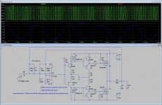
in picture one and two an weld smps with resonant zvs action build for mine welder who has a burnt transformer, and last picture a schematic of a class b like clipped amplifier used as a output stage who is from diyaudio somewhere. I also did question of a circlotron like output stage testing with dopuble coils and a feedback opamp for balanced to unbalanced..
dead time if for a audio amp also a issue because of it has to be very small, so need of very fast risetimes to get it small.
NC7SZ08 has small current so gate charge uncharce is a issue we need IR types of drivers.
regards
Attachments
Last edited:
Here's a useful fast drive. PWM input with deadtime adjustment via resistor. 8ns progagation delay. 1ns second rise and fall.
http://www.psemi.com/pdf/datasheets/pe29100ds.pdf
http://www.psemi.com/pdf/datasheets/pe29100ds.pdf
Last edited:
PWM input and deadtime adjustment via res. 8ns progagation delay.
http://www.psemi.com/pdf/datasheets/pe29100ds.pdf
This is a very fast driver? quite new, and maybe the gallium mosfets are a choise in future because speed is a problem with class D amps.
For my class-D amp project I've been looking at the following isolated design.
PWM -> NVE isolator -> dead time circuit -> driver -> fet -> speaker
Isolated surface mount PSU 12Vin, 9Vout - PDS1-S12-S9-M
Before Isolation
LDO - 12V down to 5V to power primary side of NVE isolator
After Isolation
LDO - 9V down to 5V for secondary side of NVE isolator
LDO - 9V down to 6V to power the fet driver
A little bit on the crazy side but I'm always up for doing something "different".
Last edited:
- Status
- This old topic is closed. If you want to reopen this topic, contact a moderator using the "Report Post" button.
- Home
- Amplifiers
- Class D
- Class D investigation.