Hej,
A few comments:
You cannot just put power supplies in parallel unless they are designed for it. Worst case you risk damage to the power supplies, best case you have a poor load sharing and you did not get the benefit you wanted.
A priori it looks like a problem: two 2x400W amplifiers being supplied from a single 500W power supply. But, the 400W is in 3Ohm and with 48V supply. You only have 2x35V from the power supply. It seems your amplifiers need a single supply voltage while your power supply is with symmetrical output voltages. Have I overlooked something?
What is the impedance of your speakers?
Thank you FauxFrench for responding,
Quick answer is active speakers (3way) all speakers 4 Ohm.
This mean,same one has badly advised in this tread about power supply.
It was noted as this particular amplifiers will sound best 32-34 V with higher voltage sound became harsh. Second opinion was as 250 W should be enough for one amplifier.
Looks as i have two choices to redo power supply block:
1.reuse power supply 500W-32V but one power supply for each amplifier
2.one power supply for all amplifiers ?
Is that right ?
They are really nice speakers. You say 3-way but in your posting #366 you show a setup for 2-way speakers?
I have seen "globalplayer" mention that it should be operated at some 36V not to sound harsh but I have found nobody recommending a symmetrical power supply for this Sure amplifier that is intended for a single supply voltage.
With a (single) 35V supply voltage and 4 Ohm speakers you can get some 150W per channel. With two channels (stereo) of 150W, one of your power supplies should be able to power one amplifier (if loading of only the "+" supply line is working well).
That was true then. After same experimentation have change my mind and 3 way sound more relax and precise reproducing sound.On a top it is going to be Ripol woofer. I'm doing those amplifiers to finalize "LX mini quest" post.They are really nice speakers. You say 3-way but in your posting #366 you show a setup for 2-way speakers?
For experiment and flexibility sake i will power each speaker with own amplifier and MiniDSP channel only when will make a decision about passive filters reducing 3 way speaker to two way speaker.
It is true ,that idea came from me trying be smart and saving money with out having slightest understanding in how power splay works from physical point of view.I have found nobody recommending a symmetrical power supply

Realistic evaluation. is not "harsh" sounding this amp is ca. 150 w with 35 V Dc/500 W power supply. One power supply to one amp.With a (single) 35V supply voltage and 4 Ohm speakers you can get some 150W per channel. With two channels (stereo) of 150W, one of your power supplies should be able to power one amplifier (if loading of only the "+" supply line is working well).
To get more power from this amp. is to increase to 48V DC / 400W ( manufacture recommended ) .
How amplifier will be effected increase of W, lets say 35VDC/ 1000W ?
Last edited:
It is true ,that idea came from me trying be smart and saving money with out having slightest understanding in how power splay works from physical point of view.
OK, next time buy ordinary single output power supplies for these SURE amplifiers.
Realistic evaluation. is not "harsh" sounding this amp is ca. 150 w with 35 V Dc/500 W power supply. One power supply to one amp.
To get more power from this amp. is to increase to 48V DC / 400W ( manufacture recommended ) .
Yes, 48V supply will leave a higher output power. With the present power supplies you can only run one amplifier board on one power supply PROVIDED the power supply accepts being loaded on one output (+) only and not symmetrically as it is designed for.
Take into account that with a 3-way system you will need very different output power levels for the bass/mid-range/treble. Most for the bass, less for the mid-range and even less for the treble. It makes no sense to design for several hundreds of Watts for the treble.
How amplifier will be effected increase of W, lets say 35VDC/ 1000W ?
It works differently. A certain supply voltage will leave a certain output power at the clipping point. At that clipping point you need to have the necessary current available. If you have more current than needed at the clipping point it will not leave a higher output power. That means a 35V/400W power supply and a 35V/1000W power supply will result in the same output power at the clipping point. The advantage of 35V/1000W would be that you can run 2 of the amplifier boards (2x150W + 2x150W output) on that single power supply.
The only way you can increase the output power is by increasing the supply voltage which again will demand a higher current rating.
Last edited:
Thank you from bottom of my heard FauxFrench for your advice, Im so lucky meeting you.
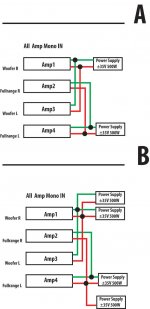
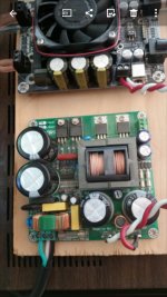
So there how power supply is going to be wired
Sure Electronics AA-AB32313 I will used for woofers .
Mid -range and treble I have amps to die for,they are just sweeties. Clean precise and neutral sound reproduction, just no nonsense.
So there how power supply is going to be wired
Take into account that with a 3-way system you will need very different output power levels for the bass/mid-range/treble. Most for the bass, less for the mid-range and even less for the treble. It makes no sense to design for several hundreds of Watts for the treble.
Sure Electronics AA-AB32313 I will used for woofers .
Mid -range and treble I have amps to die for,they are just sweeties. Clean precise and neutral sound reproduction, just no nonsense.
Hi,
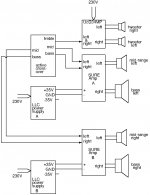
I will suggest you to implement the system shown in my sketch.
It uses two of the four SURE amplifiers you already have, the two LLC (+/-35V) power supplies you already have and one UcD34MP amplifier with power supply you may have to buy.
Why you bought four stereo SURE amplifiers I do not understand.
If you decide for a two-way system instead, you remove the UcD34MP module and the tweeters from the sketch and turn the mid-range into mid-range&treble.
Attachments
I like your drawing very much and I have a feeling my experimentation at the end will be set up like in you drawing.
Those was two reasons why I did it and those was my original thoughts :
1. I got four amps for price of two,just cant say no to such deal.
2. Have had a plan that SURE stereo amp. to use as a mono. As a bonus would be better left and right signal separation I have no idea how god channel separation those SURE amps has,but using as a mono will do pretty god job separating left and right signal.
I don't understood my self in the beginningWhy you bought four stereo SURE amplifiers I do not understand.
Those was two reasons why I did it and those was my original thoughts :
1. I got four amps for price of two,just cant say no to such deal.
2. Have had a plan that SURE stereo amp. to use as a mono. As a bonus would be better left and right signal separation I have no idea how god channel separation those SURE amps has,but using as a mono will do pretty god job separating left and right signal.
Attachments
Last edited:
Hi gin,
Those was two reasons why I did it and those was my original thoughts :
1. I got four amps for price of two,just cant say no to such deal.
A VERY valid reason, I would have done the same.
2. Have had a plan that SURE stereo amp. to use as a mono. As a bonus would be better left and right signal separation I have no idea how god channel separation those SURE amps has,but using as a mono will do pretty god job separating left and right signal.
Careful now - you cannot just combine a stereo amplifier to a mono amplifier without considering the amplifier design.
PBTL of already BTL coupled amplifiers rely on exact synchronized control of the output power switches. According to the datasheet it should actually be possible. Delicate work on a PCB with an SMD-type power bridge. You would gain no power as explained before.
Bridging of SE configured amplifiers is possible if they can handle the bridge currents. But, your SURE amplifier is already bridged (BTL) so that is not an option for you.
Last edited:
Hej,

I'm an industrial designer (dying out species - modern T.Rex ) and I do understand up to same level.but after that PURE RESPECT to a guys who do actual witch craft with oscilografs and things sticking bunch wires from.
Now that i was planing..
All my equipment is wired as balanced or floating chassis input using XLR connectors (no idea why I'm saying that probably would like to make an impression ).
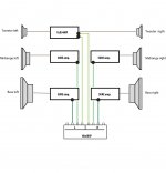
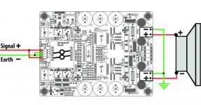
I dot know if such wiring can be called bridge BTL ,I guess it could be called pseudo BTL but it should look like this
This is exactly that i was scared off ...To me is WHICH CRAFT ... NASADelicate work on a PCB with an SMD-type power bridge. You would gain no power as explained before.
Bridging of SE configured amplifiers is possible if they can handle the bridge currents
I'm an industrial designer (dying out species - modern T.Rex ) and I do understand up to same level.but after that PURE RESPECT to a guys who do actual witch craft with oscilografs and things sticking bunch wires from.
Now that i was planing..
All my equipment is wired as balanced or floating chassis input using XLR connectors (no idea why I'm saying that probably would like to make an impression ).
I dot know if such wiring can be called bridge BTL ,I guess it could be called pseudo BTL but it should look like this
Attachments
Last edited:
Hej,
I once had a course given by an early industrial designer, Mackeprang. Very creative and rational working method. Much appreciated.
Electronics: Your "pseudo BTL" is more pseudo than BTL.
BTL (Bridge Tied Load) was probably invented to increase the output power in cars where the voltage was limited to 12V. Traditionally, with one amplifier, the voltage swing (positive and negative) had to remain within the supply voltage (evidently). Thus, "zero" was defined as half the supply voltage and the voltage swing could ideally be half the supply voltage in the positive direction (where it was limited by the positive supply voltage) and half the supply voltage in the negative direction (where it was limited by the negative supply voltage). With only 12V available, thus ideally 6V swing to each side, the electronic engineers used the method of the industrial designers and realized the 12V was an absolute constraint while they had another parameter available: What if we let one speaker terminal go in positive direction and the other go correspondingly and simultaneously in negative direction such that we can use the full supply voltage (and not only half the supply voltage) at any moment? The idea of BTL was born. Technically, we describe it as two amplifiers simultaneously working in counter-phase. Today, a trick used by most class D chips. The speaker is connected between two amplifier output terminals operating in counter-phase (and no more with a connection to ground).
What you show in your sketch is two amplifiers connected in parallel at both input and output. I cannot see "+" and "-" at the four input terminals but either the two amplifiers will work in phase or in counter-phase.
Your outputs are connected in phase (plus to plus and minus to minus).
If the inputs are connected in counter-phase, one amplifier will be told to go positive while the other negative at the same moment. But as the outputs are connected by a low impedance short circuit, the amplifiers will fight one another with high short circuit currents. No good.
If the amplifiers are connected in phase, they are both told to go positive (or negative) but, with a slightly different gain in practice, they disagree on how much. Again, they fight one-another with current running from one amplifier and into the other. We call it cross-currents. Still no good.
Real and useful BTL is only two output terminals from two amplifiers, each connected to a (different) terminal of the speaker, and working in counter-phase. Even if they have a different gain it does not matter because adding two sine-wave signals results in another sine-wave signal. The only current path is through the speaker and cross-currents are not possible as with parallel connection.
Our ways of working are basically the same systematical logic used by industrial designers.
Last edited:
You know, just must admit, Im having a blast time with you on this tread...
No one jumps in with a comments out of topic range and starts to talk about relation ship with his grandmother... I'm learning enormously a lot from you.
Loving it..
Dam god explanation on BTL anybody can understand.
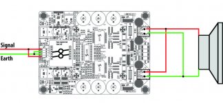
There is a sketch what I understood should be right way bridge wire SURE stereo amplifier to mono.
No one jumps in with a comments out of topic range and starts to talk about relation ship with his grandmother... I'm learning enormously a lot from you.
Your "pseudo BTL" is more pseudo than BTL.
Loving it..Dam god explanation on BTL anybody can understand.
There is a sketch what I understood should be right way bridge wire SURE stereo amplifier to mono.
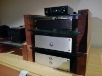
Just today have redesigned my stereo rackThe speaker is connected between two amplifier output terminals operating in counter-phase (and no more with a connection to ground).
Attachments
Last edited:
You have well understood my explanation about BTL in general. One output from each of two amplifiers, operating in counter-phase, and each amplifier output connected to a terminal of the speaker. Fine.
But, a detail I did not mention for the SURE design - it is already BTL-coupled. While your two outputs will function, the two other outputs you show as connected to ground each have a signal in counter-phase with the outputs you use. You effectively short-circuit two active amplifier outputs to ground. That will not leave a good result. You can leave these to outputs open (unconnected) and it will work as if you used the two outputs from one of the amplifiers - thus nothing gained by using two amplifiers.
I believe I explained above, in a little detailed manner, that amplifiers that are already BTL-coupled can only be turned into mono by PBTL-coupling or use of only one channel.
PBTL coupling of two BTL amplifiers is not something you can do at the terminals of the amplifier boards - it requires a change of the amplifier design meaning modifying the PCB-tracks, removing components and eventually adding components. Unless you are experienced with such, I will not recommend you to try, in particular on a board with SMD components.
Elegant, simple and functional stereo rack.
Last edited:
Dear Faux French,
thank you from bottom of my heard for conversation,advice and valuer lessons ,those be not be forgotten.
Anything I can do for you just let me know from logo design to enclosures for amps or same thing like that.
I think we have explode all possible wiring fro SURE amp-no BTL´s for this model.
Strangely, only right know I recall reading on SURE or WONDOM FAQ about they T-Amp line and same one has asked about BTL possibility and an answer was as BTL is not possible on T-Amp line amplifiers.
Faux French,I will send you an invitation when tread "Lx mini quest " be finished.
Wow, OP here, this thread really took off! I am still loving my AA-AB32313, just refoamed my L-65's incidentally I upgraded my woofers to 2214h and tuned my port to spec, vast improvement in bass in all ways, and they mesh perfectly with the other drivers, in case anyone is interested.
The 2214h are hungrier however and I'm thinking of building a dual mono amp this time. Question, is there a Sure offering with the same chipset and topology that does a realistic 400w/channel or more?
I've been looking but it's not easy to figure out. I could build an icepower big-power setup, but that's much more expensive and I like these cheap Sure boards. Is this amplifier the limit for this chipset?
Forgive me for asking this, but how could this be built to limit the amount of output power? I am really interested in building an amp around this board after reading this thread, but I have a small apartment and my DIY speakers don't want much more than 50w tops!
I was previously using a 750w power amp turned down fairly low when I was between amps, but even with an 80w amp, i don't have quite as much control over the lower volumes as i would like....
Maybe i need to stay low wattage? I don't want to restrict the SURE by using a low voltage PSU.
I was previously using a 750w power amp turned down fairly low when I was between amps, but even with an 80w amp, i don't have quite as much control over the lower volumes as i would like....
Maybe i need to stay low wattage? I don't want to restrict the SURE by using a low voltage PSU.
- Home
- Amplifiers
- Class D
- Sure Electronics AA-AB32313 2x400