hi everyone. I am working on class D amplifier for which I used following things.( I can buy products from only www. dnqtechindia .com)
1) NE567 (100KHz triangular wave generator)
2) LM393 (for modulation)
3)SN74LS86AN (for delay time between high and low side mosfet)
4)TL082 (for audio low pass filter 10KHz)
But I am very confused with the output power stage
For mosfet I have the following mosfet
1) IRFZ44N
2) F9540 (yes only f9540 printed on the mosfet)
3) IRF540N
For driving mosfet-
my first choice is
using two tc4420(non inverting driver ic peak 6A!)
with one connected to high and other to low.
and the out put of both connected to a GATE drive transformer primary with a resistor(10ohml and capacitor(1uF)
and four secondary for each mosfet with a proper resistor and a high speed diode in reverse for fastet turn off.
my second choices-
is using p and n channel mosfet for making a h bridge and driving using two tc4420 gate driver ic.
My question is the any above configuration will work Or I should go with IR2110.
I AM NOT NEW TO ELECTRONIC BUT NOT A PRO.
I CAN ACCESS TO A CRO (25MHz)
(I am going to use a 1kohm resistor between mosfet gate and source)
please help sugges me.
Thanks
Hi,
A simple gate driver transformer can't transmit the DC component of the PWM signal. You have to restore it by for examle a clamping network. And because of the leakage inductance you need a current amplifier stage. And duty cycle must be limited. The second idea is less demanding, but still there are tasks hidden... try in simulator! I built something similar 10+ years ago, but first i shifted level and then drived gates.
CRO->oscilloscope. This is the first time I saw this abbrev. Dont use it!
LM393 is quite slow.
Last edited:
Hi,
A simple gate driver transformer can't transmit the DC component of the PWM signal. You have to restore it by for examle a clamping network. And because of the leakage inductance you need a current amplifier stage. And duty cycle must be limited. The second idea is less demanding, but still there are tasks hidden... try in simulator! I built something similar 10+ years ago, but first i shifted level and then drived gates.
CRO->oscilloscope. This is the first time I saw this abbrev. Dont use it!
LM393 is quite slow.
thanks for reply
1) how can I restore the dc component of pwn by the network any circuit diagram or link may help
2)what are other alternatively for lm393 (will lm311 or tl082 work?
sorry for bad English my mother toungh is HINDI.
Figure 3 shows DC restoration:
Gate Drive Transformers vs. Fully Integrated Isolators in Isolated DC-DC Power Converters | EE Times
And figure 1 is a current amplifier:
Power Tip 42 (Part 1): Discrete devices-a good alternative to integrated MOSFET drivers | EE Times
For VCC you can rectify the secondary voltage.
Basically Figure 3 in the second article is good for your application, just with much less capacitance, because duty cycle can vary fast, and the reference output voltage should not be the capacitor midpoint, but collector of Q2.
So it is possible to make it. But basically an integrated half bridge driver is much less problematic and cheaper.
LM311 or LM319 is good. However there are better and still cheaper solutions also. For example CD4069UB can be used as comparator in both triangle generator and PW modulator section.
TL082 is not a comparator but an OPA.
If you want to experiment then build whatever you are able to understand. But if you need a good, simple, and cheap solution, then UcD (search in DIY audio) is the best option.
DNAtech is a very limited source. Can't you really buy from element14 or Ebay? element14 India | Electronic Components Distributor | Premier Farnell Group
Figure 3 shows DC restoration:
Gate Drive Transformers vs. Fully Integrated Isolators in Isolated DC-DC Power Converters | EE Times
And figure 1 is a current amplifier:
Power Tip 42 (Part 1): Discrete devices-a good alternative to integrated MOSFET drivers | EE Times
For VCC you can rectify the secondary voltage.
Basically Figure 3 in the second article is good for your application, just with much less capacitance, because duty cycle can vary fast, and the reference output voltage should not be the capacitor midpoint, but collector of Q2.
So it is possible to make it. But basically an integrated half bridge driver is much less problematic and cheaper.
LM311 or LM319 is good. However there are better and still cheaper solutions also. For example CD4069UB can be used as comparator in both triangle generator and PW modulator section.
TL082 is not a comparator but an OPA.
If you want to experiment then build whatever you are able to understand. But if you need a good, simple, and cheap solution, then UcD (search in DIY audio) is the best option.
DNAtech is a very limited source. Can't you really buy from element14 or Ebay? element14 India | Electronic Components Distributor | Premier Farnell Group
again thanks for reply
got ever thing you want to explain about gate driver. all clear.
but still problem about modulation
you suggest me to use to cd4069 but I think it has only one input.
any diagram of circuit will help.
also can't find any circuit diagram of lm319 as a modulator.
I can't order components from elements 14 because shipping charges are almost 5 TIME the cost of the components I try to order.
Buy more components at once, and try to join to somebody else who also needs some components!
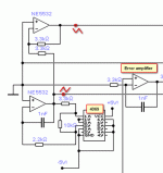
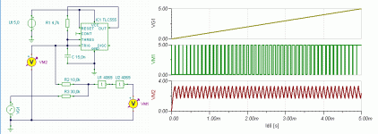
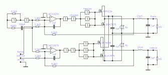
I attached some schematics showing inverter (like 4069) used as modulator, clock generator.
But you can also use it as error amplifier just like an inverting OPA. You can imagine it as a weak, a little noisy, but fast OPA where the noninverting input is hidden inside, and tied to (VDD+VSS)/2. So if VDD and VSS are clean and symmetrical, then this can be used as an inverting OPA circuit.
Attachments
Last edited:
- Status
- This old topic is closed. If you want to reopen this topic, contact a moderator using the "Report Post" button.
- Home
- Amplifiers
- Class D
- needed help in class D amplifier gate driver circuit.


