Over on danielwritesbac's thread about the TDA8932 there's some interest in winding one's own input trafo for these chips so here's my quick-and-dirty guide to saving yourself a fair wad of cash (at the expense of your time) in building your own transformer. Their audible advantages are already taken as read so here I'm just going to deal with the steps to be taken, with the absolute minimum of math.
Step 1 - what frequencies do you need your transformer to pass?
You only need to be concerned with the low-frequency end as the top will look after itself. Transformers get bigger (and generally need more turns) the lower their working frequency so if you want to end up with the smallest possible size, don't ask your creation to deal with more LF than you absolutely need.
For the purposes of this example I'll assume you want to go down to 20Hz at full level, but no lower. The trafo can handle lower frequencies than that but only at reduced amplitude.
Once you've answered this initial question you can move on to calculate the Volt-seconds for your design. This is a crucial parameter in the design, the more V-s the more turns of wire you have to put on, given a particular physical size of trafo.
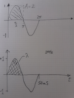
I've made a sketch of how to calculate the V-s parameter given your answer to the first question. The top squiggly line is my attempt at a sinewave with a geometrical horizontal axis, the lower one is what you might see on a scope with time as the X-axis. I'm showing the first one because we typically use calculus to determine the area under a curve, the area calculation is what's need to determine V-s, shown as the Greek letter 'lambda'. The lower wave shows a time axis - with 20Hz the whole cycle takes 50mS, for an amplitude of 1V peak, the V-s in the hatched area comes out to be 0.0159.
I got this result by using the area calculation from calculus which says the area under the sine is 2/Pi times the horizontal dimension (25mS in this case).
Step 1 - what frequencies do you need your transformer to pass?
You only need to be concerned with the low-frequency end as the top will look after itself. Transformers get bigger (and generally need more turns) the lower their working frequency so if you want to end up with the smallest possible size, don't ask your creation to deal with more LF than you absolutely need.
For the purposes of this example I'll assume you want to go down to 20Hz at full level, but no lower. The trafo can handle lower frequencies than that but only at reduced amplitude.
Once you've answered this initial question you can move on to calculate the Volt-seconds for your design. This is a crucial parameter in the design, the more V-s the more turns of wire you have to put on, given a particular physical size of trafo.
I've made a sketch of how to calculate the V-s parameter given your answer to the first question. The top squiggly line is my attempt at a sinewave with a geometrical horizontal axis, the lower one is what you might see on a scope with time as the X-axis. I'm showing the first one because we typically use calculus to determine the area under a curve, the area calculation is what's need to determine V-s, shown as the Greek letter 'lambda'. The lower wave shows a time axis - with 20Hz the whole cycle takes 50mS, for an amplitude of 1V peak, the V-s in the hatched area comes out to be 0.0159.
I got this result by using the area calculation from calculus which says the area under the sine is 2/Pi times the horizontal dimension (25mS in this case).
Attachments
Last edited:
Step 2 - what maximum amplitude signal do you need to handle?
Armed with our V-s value, calculated for a 1V peak signal, the second step is to scale this up by whatever peak voltage we need to deal with. With a working signal level of 2VRMS, that will be 2 * sqrt(2) = 2.82V.
So our design value for V-s is 0.045 (rounded to 2 sig figs).
Armed with our V-s value, calculated for a 1V peak signal, the second step is to scale this up by whatever peak voltage we need to deal with. With a working signal level of 2VRMS, that will be 2 * sqrt(2) = 2.82V.
So our design value for V-s is 0.045 (rounded to 2 sig figs).
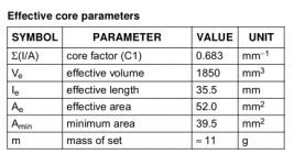
Step 3 - choose your transformer core and extract its Amin value.
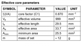
Here I'm dealing with the EP17 core, its Amin is shown in the table as 25.5mm^2. Convert this to cm^2 by dividing it by 100, hence we have 0.255 cm^2.
There may be some iteration involved here if you're new to the game and have no feel for what core sizes will work given certain requirements. For example if you're pushing your luck and want the ultimate smallest size you may find when you get to work out what diameter wire you need its unavailable from the normal sources due to being too small to handle without breaking.
The EP17 isn't really optimized here because if you look at the table, the Amin is quite a bit smaller than the Ae. This is telling us the magnetic path isn't a constant cross-section meaning the narrow part is the weak link in the chain. Ideally Amin would be almost identical to Ae.
Attachments
Abraxalito, thanks for taking the time to teach us the art of rolling your own trafos! It is not limited to class D as I want to use this to make a balanced input driver for a class A amp over in this thread by Kees:
http://www.diyaudio.com/forums/solid-state/291767-allfet-circlotron.html

http://www.diyaudio.com/forums/solid-state/291767-allfet-circlotron.html
Is this a joke?Step 1 - what frequencies do you need your transformer to pass?
You only need to be concerned with the low-frequency end as the top will look after itself.

High frequency even response is *the* hard part and stumbling block in Audio transformers.
Even unsophisticated designs can reach low frequencies, just use the brute force method, add wire and iron until you have enough inductance.
That very same approach will *destroy* HF performance, right inside the Audio band, unless you are a very careful and experienced designer and know how to counteract that
The fact that the transformer will be used with a Class D power amp instead of other conventional Audio devices which have been studied for close to 100 years does not change the main problem.
If what you say were true, cheap power transformers, rated for 50/60 Hz operation would make for quite good Output transformers and so on ... clearly not the case.
Step 4 - plug the numbers into the transformer equation to obtain the turns number
Here's the equation to determine how many turns of wire the primary of our transformer needs, the primary being the input side.
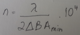
On the left of the equation 'n' is the number of turns for the primary. On the right, the numerator is our calculated V-s, denoted by 'lambda'.
The denominator has 2*deltaB*Amin. Here 'deltaB' is the peak flux that the core material can handle. With ferrite this is a fairly strong function of temperature, but since we're only handling signal levels the trafo itself won't be generating any heat so we can go with a deltaB value of 0.35T (units are Tesla). Some ferrites can handle more than this - if you know you've got a core material which can go higher (some reach 0.5T) then put that number in. If you're not sure of the core material then I'd suggest using 0.35. For high mu core materials this number is nearer to 0.25. Amin we've already found from the core data.
With our EP17 putting all the numbers in turns out an 'n' value of 2521. This agrees pretty closely with the number of turns I needed simply by inspecting the waveform on my 'scope and feeding in a 20Hz sinewave and looking for visual distortion - the sign of the onset of saturation.
Here's the equation to determine how many turns of wire the primary of our transformer needs, the primary being the input side.
On the left of the equation 'n' is the number of turns for the primary. On the right, the numerator is our calculated V-s, denoted by 'lambda'.
The denominator has 2*deltaB*Amin. Here 'deltaB' is the peak flux that the core material can handle. With ferrite this is a fairly strong function of temperature, but since we're only handling signal levels the trafo itself won't be generating any heat so we can go with a deltaB value of 0.35T (units are Tesla). Some ferrites can handle more than this - if you know you've got a core material which can go higher (some reach 0.5T) then put that number in. If you're not sure of the core material then I'd suggest using 0.35. For high mu core materials this number is nearer to 0.25. Amin we've already found from the core data.
With our EP17 putting all the numbers in turns out an 'n' value of 2521. This agrees pretty closely with the number of turns I needed simply by inspecting the waveform on my 'scope and feeding in a 20Hz sinewave and looking for visual distortion - the sign of the onset of saturation.
Attachments
Step 5 - figure out what size of wire is needed for the primary
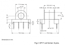
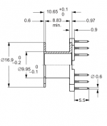
We choose the wire size to make the best use of the available space on our bobbin, called 'the winding window'. I've clipped the part of the data for the bobbin - I find that its best to check the mechanical data very thoroughly to determine the size of the 'winding window' - oftentimes if this value is given, its in error, so going back to first principles is what I do.
From the diagram the important dimensions are the inner diameter, the outer diameter and the height. Subtract the inner from the outer and divide by 2. Multiply the result by the height, this gives us the area of our winding window. For the EP17 the relevant numbers are 11.4, 7.2 and 9.4. I get 19.74mm^2.
Next, apportion this area between our two windings, primary and secondary. Since the primary will be on the inside it'll have shorter turns, meaning lower resistance -if I'm building an output transformer (for headphones) I'll give it 40% of the available area. But with a signal transformer, as here, optimizing the losses between primary and secondary windings is far less crucial. Sometimes the fact that wire isn't available in every possible diameter means its best to reverse the order and put the secondary on first, it can make better use of the available space. Or I may well give the primary more space simply because it has more turns and thinner wire isn't available (or is too likely to break) to fit it into just 40% of the space.
However I'll work this example through aiming to optimize the resistances between the two windings and go for a primary which only occupies 40% of the space. 0.4*19.74 gives 7.9mm^2. To fit 2500 turns into this area means each turn takes up 3.2*10^-3 mm^2. Take the square root of this number to get the external diameter - 0.056mm. Gulp! This is very thin wire and not widely available - note the gauge of wire is thinner than the external diameter by twice the insulation thickness.
When this happens and the transformer is a signal transformer one solution is to 'steal' available space from the secondary. If the transformer is step-down, this can be done, if its step-up it'll be impossible because for a step-up transformer the secondary needs even thinner wire than the primary.
So let's check to see if our transformer is a step-down, meaning the output voltage is lower than the input. To answer that we need to go to the TDA8932 datasheet....
Attachments
Is this a joke?
High frequency even response is *the* hard part and stumbling block in Audio transformers.
Even unsophisticated designs can reach low frequencies, just use the brute force method, add wire and iron until you have enough inductance.
That very same approach will *destroy* HF performance, right inside the Audio band, unless you are a very careful and experienced designer and know how to counteract that
The fact that the transformer will be used with a Class D power amp instead of other conventional Audio devices which have been studied for close to 100 years does not change the main problem.
If what you say were true, cheap power transformers, rated for 50/60 Hz operation would make for quite good Output transformers and so on ... clearly not the case.
Perhaps we make assumption that these are small signal transformers the limiting factor is then the low end which is where we need to address first?
Step 6 - how many turns do we need on the secondary?
Going over to the TDA8932 datasheet, its maximum output swing will be when running from the maximum recommended supply of 36V. There's no issue running at this voltage as that's not its design limit, rather above this there's an over-voltage protection circuit that'll kick in.
Another piece of data we need is how close to the supply rails can its output swing, this depends on how short a pulse it can produce (about 80nS) together with the load impedance seen and the on resistance of the output FETs. Since the end user will choose the output load it's best to assume infinite load impedance for the purposes of setting the input level so only the maximum mark-space ratio is of any consequence (about 97% for 320kHz switching speed). Thus a 35V peak output can be achieved unloaded, in conjunction with the 36dB gain we need a 555mV peak input signal to reach clip.
Taking the ratio of the peak secondary voltage (555mV) to the peak primary voltage (2.82V) gives us the turns ratio - 5.1 : 1. Say 5:1 which gives 500 turns for the secondary. Given the balanced input this will be centre-tapped at 250turns.
Step 7 - finally deciding on the primary wire diameter needed.
For a fully optimized (in terms of copper losses) transformer, the resistance of the secondary would be N^2 (here N = 5, so 25) times lower than the primary, hence be wound with thicker wire to occupy about 60% of the available winding window. However we've already found that this calls for impracticably thin wire for the primary. With so few turns on the secondary needed we're comfortably in the position of being able to 'steal' winding space from our secondary to allow thicker wire to be used on the primary. I went for 0.07mm wire - this same wire can then be also used on the secondary. Its external diameter is 0.085mm according to my micrometer which means the total winding space required for 3000 turns is 21.7mm^2.
The eagle-eyed reader will note that this exceeds our calculated winding window area by about 2mm^2. Turns out that the winding can go beyond the confines of the bobbin somewhat, the hard limit is the inner diameter of the ferrite which measures at 11.9mm (rather than the 11.4mm for the outer diameter of the bobbin). But I also used fewer turns because I did the turns calculation empirically. If you're doing this by the book I'd recommend you go for 0.06mm wire or relax the LF specification somewhat to allow fewer turns. Beginners would be advised to leave themselves comfortable margins for untidy windings
For those who don't much warm to the idea of their first transformer build using such fine wire as 0.06mm (it took me many winds to get up the courage to order up such thin wire myself) there's the alternative of using a larger sized core.
RM8 looks to be a suitable choice, I've attached the vitals for its core and bobbin. Note the Amin of 39.5mm^2 compared to 25.5 for the EP17, the number of turns required scales in direct proportion to the ratio of these two figures. Hence with RM8 we'll need 1600 turns for the primary and 320 for the secondary. The winding window works out to be 30.7mm^2, which for an optimized wind means 0.07mm wire for the primary, but winding with just one wire diameter for convenience means 0.1mm wire works fairly comfortably.
RM8 looks to be a suitable choice, I've attached the vitals for its core and bobbin. Note the Amin of 39.5mm^2 compared to 25.5 for the EP17, the number of turns required scales in direct proportion to the ratio of these two figures. Hence with RM8 we'll need 1600 turns for the primary and 320 for the secondary. The winding window works out to be 30.7mm^2, which for an optimized wind means 0.07mm wire for the primary, but winding with just one wire diameter for convenience means 0.1mm wire works fairly comfortably.
Attachments
Last edited:
Perhaps we make assumption that these are small signal transformers the limiting factor is then the low end which is where we need to address first?
Signal transformers are indeed rather a different beast from power transformers. The latter need much more attention paid to losses. Its quite possible to use ferrite cored transformers to drive headphones but I've stayed away from using them for bass/mid duty on speakers as the maximum flux they can support is low, meaning they need to be massive. Far better to stick with steel cores for bass duty. For mids and tweeters though, ferrite works a treat. When building an active system, I'd not go direct to a tweeter any more as transformers sound so much sweeter.
@doctormord - not yet found a need for mumetal screening, but its wise to keep these signal trafos well away from any power transformers.
Last edited:
I was winding my own choke last night (for a filter in a power supply) and found that the measured inductance is non linear with number of turns in a ferrite toroid (30mm OD x 18mm ID x 12mm tall). Maybe this is old news to most? I did 8 turns of 18ga magnet wire and got 0.8mH and I wanted a 2.2mH choke so I added about 2x more length (thinking about 3x turns will be about right value) and so I got 27 turns and then measured 11mH! Way more than I needed but was actually a very compact 11mH 18ga choke and now I wanted to use it for a compact low pass XO filter at speaker level signals. Why don't we see more commercial off the shelf speaker inductors with this kind of construction? It only measured 0.2ohm DCR - an excellent value considering the rather high 11mH value. All measured with my DATS in LCR mode.
Here is ferrite core I used:
http://m.aliexpress.com/item/32450300252.html
Final question - can this type of core be used to wind signal trafos with thin or fine gauge wire?
Here is ferrite core I used:
http://m.aliexpress.com/item/32450300252.html
Final question - can this type of core be used to wind signal trafos with thin or fine gauge wire?
Last edited:
The inductance you get is directly proportional to the number of turns squared. So let's check with your result - 8 turns gave you 800uH so the AL value (normally the units are nH/N^2) then is 800000/64 = 12500. Plugging that into the situation with 27 turns, you should get 9.1mH.
The problem with such high AL value cores is they'll saturate at jolly low currents - for speaker level XOs you'll want a gapped core so it probably won't be a toroid. Though some gapped ferrite toroids do exist they're not really common in my experience.
Yes you can use ferrite toroids to make transformers but they're a devil to wind thousands of turns around.
I have these CMC from Coilcraft. I think the ferrite is gapped as I can see a joint held together by glue. There is some strange looking mu metal shield between the two windings?
This is a very compact 25mH choke rated for 3A - would it saturate less easily?
http://www.coilcraft.com/comoco.cfm
P3717-Al model.
Yes, winding 2400 turns of 0.06mm wire on a toroid would drive one insane.
This is a very compact 25mH choke rated for 3A - would it saturate less easily?
http://www.coilcraft.com/comoco.cfm
P3717-Al model.
Yes, winding 2400 turns of 0.06mm wire on a toroid would drive one insane.
Last edited:
A CMC (common-mode choke) is an entirely different beast from a choke. It has 4 terminals, not two and is designed to have equal but opposite currents flowing through its two windings. As a result the 25mH inductance is only seen by currents which unbalance the cancellation effect. Its of no use as a choke in a speaker XO, it has a very particular application to prevent common-mode noise, normally on a mains supply.
I'll take a look to see if Mouser's stocking any gapped cores which you might be able to use.
http://www.mouser.com/ProductDetail/EPCOS-TDK/B65887E400A41/?qs=sGAEpiMZZMs2JV%252bnT%2fvX8JpxZdCKKXlR%2fsERLQf0kY4%3d
These might do the trick, the AL value is 400nH. So as you want 11mH that will take 166turns. Not too outrageous. If I look further into the spec I might even be able to predict the DCR for you.
Quick back of the envelope calculation - you need 12m of 0.72mm dia wire and it'll be about 0.5R DCR.
Last edited:
If you just used half the CMC (I know it's a waste) but wouldn't that provide the correct measured inductance?
12m is a lot of wire to wind on a donut. What's wrong with using the non-gapped toroid in a passive XO? Aren't the currents AC, so saturation is not as big an issue? Speaker currents are less than 2 amps typically.
Am I not basically building a lower power version of one of these monsters used for speaker level signals?
http://www.parts-express.com/jantze...oil-toroidal-inductor-crossover-coil--255-836
The core I linked to isn't a donut, it comes with a bobbin. You could put on 166 turns by hand in a few mins.
CMCs aren't designed to operate with appreciable current imbalance so chances are if you wanted just to use one side, it would saturate quite quickly. CMCs in my experience have very slim core cross-sections - no reason to spend money on core when their application is going to give rise to very low flux levels.
Give your green toroid a listen, I'd bet you'll hear the 'cracking' sound of a ferrite going into saturation. If not, then you've gotten yourself a cheap inductor.
With your link it says the core's iron but I can't find any details - could be powdered iron.
- Status
- This old topic is closed. If you want to reopen this topic, contact a moderator using the "Report Post" button.
- Home
- Amplifiers
- Class D
- Designing a classD amp input transformer - step by step guide