I see I'm not the only one who do not now what I do wrong, because nobody do help.
I am quite busy with some other projects... For real help I have to put in spice also what you did and comment. But can not at the moment, I will for sure in future continue with class D
For example for BD modulation I do not see which voltage nodes are represented by image graph you attached, because votlage nodes are not represented on spice schematics, only current through elements. (also need spice chematics in asc form too see nodes)
So I dont know what graph you attached respresent..
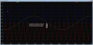
In general complete half period of sine only "a+" short work, and other half period of sine only only "a-"
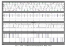
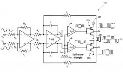
In general you should have "triangle in half wave"(triangle with DC component better to say) , top period of sine is compared to top half wave wave of triangle, and bottom period of sine with bottom half wave of triangle.
Or you complement sine and compare with "normal triangle".
Of course in "self oscilating class D" there is no "external triangle", so you have to complement sine.
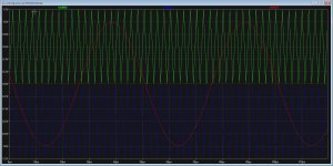
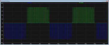
Can you show pwm1+ and pwm 1- ?
Last edited:
Hi grizlek
Thanks for responding, As I did read in some papers I do nothing wrong, but you say offset or dc components are the important things who is needed for this kind of amp.
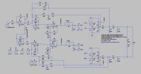
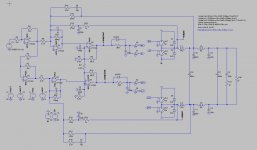
Yes I did complement two sines and one normal triangle, because this is what the book says, see last picture. but this schematic has a self oscillation and no trangle generator.
But has uge shoot through because signals are not right.
I did already has the idea like you that offsets are needed, otherwise I get trouble. Are there not
You see also 3 layer modulator but also higher orders, these move the distortion up, never see someone tried it with audio. Also here we need steps in dc setups then? like triangle has multiple sections on dc levels.
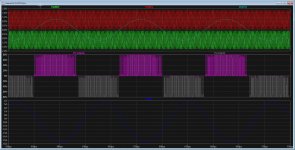
Middle pic you see upper and lower bridge, and signals who cause uge shootthroughs, delayen one bridge can help but do not get wel for out signal I gess,.
Thanks for responding, As I did read in some papers I do nothing wrong, but you say offset or dc components are the important things who is needed for this kind of amp.
Yes I did complement two sines and one normal triangle, because this is what the book says, see last picture. but this schematic has a self oscillation and no trangle generator.
But has uge shoot through because signals are not right.
I did already has the idea like you that offsets are needed, otherwise I get trouble. Are there not
You see also 3 layer modulator but also higher orders, these move the distortion up, never see someone tried it with audio. Also here we need steps in dc setups then? like triangle has multiple sections on dc levels.
Middle pic you see upper and lower bridge, and signals who cause uge shootthroughs, delayen one bridge can help but do not get wel for out signal I gess,.
Attachments

I think you did reference on this, what concerns the triangle, I did read somewhere that als it can be done with input sinusoidal audio signal but that looks to me it is not recommended.
Attachments
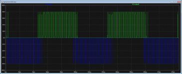
Huh.. but there should be no shoot through if logic is fine : PMW1+ and PWM1- should never work in the same time..
But, neglect my comment so far.. still not able to make tests for full respond .
.
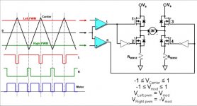
If audio signal mixed with feedback (input of U5 and U6) is above 0V, only pwm 1+ should work, and if below 0V only pwm 1- should work.. if this is the case there shall be no shout through ? hmm
BD moduation is 3 level modulation.. Vcc -Vcc and 0V
What is the function of U5 /U6?.. we need block that when input signal + modulation feedback is above 0V we make only pwm+ working and opposite..
But, neglect my comment so far.. still not able to make tests for full respond
.If audio signal mixed with feedback (input of U5 and U6) is above 0V, only pwm 1+ should work, and if below 0V only pwm 1- should work.. if this is the case there shall be no shout through ? hmm
BD moduation is 3 level modulation.. Vcc -Vcc and 0V
What is the function of U5 /U6?.. we need block that when input signal + modulation feedback is above 0V we make only pwm+ working and opposite..
Last edited:
Kees, I have other idea, I wonder can three of such UCD-s be used for 3 phase motor control, but without any mictroncontroller or logic.
Self oscilating loop using current feedback what will vary frequency and voltage of 3 phase sine generator accordingly.
Hi Grizlek
Thanks for the respons, I do also be a little confused about why it do not work, as I see in the schematic examples is the triangle on the comparators just a version without offset, what I did see somewhere else is a + - 4 volts pp triangle who a input sinusoidal signal in fase, one above 0 and one beneath 0 like in pic.
Attachments
Seen versions with 3 level modulation and triangles, self oscillating is difficult, except when you build 3 class d amps and feed 120 degree fase shiftes sinusoidal signals, this can be done with pic, or maybe delays into the switching part of amp, then you need logic.
With arduino and program
arduino control 3 phase inverter
or here
Three phase inverters
The making of fase shifted 50 hz signals are difficult, need a lookup table, or maybe integrators?.
regards
With arduino and program
arduino control 3 phase inverter
or here
Three phase inverters
The making of fase shifted 50 hz signals are difficult, need a lookup table, or maybe integrators?.
regards
for motor inverter three fase.
Lecture 25 Pulse-Width Modulation (PWM) Techniques - ppt video online download
And here I have some things getting when combine some stuff, get pretty low distortions then but no three level as I see. Three level introduce crossover distortion like a normal amo, we need to use pulses around the zero crossings bias the coil.
Attachments
@grizlek
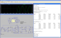
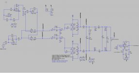
I have seen that for three level needs indeed offset, I can use two triangles in opposite fase or one with two input signal in opposite fase, but both needs offset. I have made two triangles with a extra opamp who do work nicely by shifting the two, I can even overlap a little, getting a kind of bias for the switch stage.
Maybe I can even use a special buck kind of stage?, then it looks like a class ab amp system who do now switch.
Have include more pics, maybe it is even possible I use wrong comparators, types who do not go negative, strange stuff.
Also the voltage on output is a mess, but the current is a nice signal, even with low distortion for a open loop, was -70dB 12 amps out, so even more strange..
regards
regards
Attachments
Last edited:
anti cross-conduction
I maybe thought of something you can try. First, before I could mention it, I checked on the IR2010 information, determining that it is dv/dt immune. Given that, an inductor, say 50nH, is put in series with the drain of the bottom MOSFET. A diode goes parallel with that (cathode on positive side of choke) to allow resetting after the shoot-through current spike. If you feel it works well enough you might go back to the common method of modulation.
I maybe thought of something you can try. First, before I could mention it, I checked on the IR2010 information, determining that it is dv/dt immune. Given that, an inductor, say 50nH, is put in series with the drain of the bottom MOSFET. A diode goes parallel with that (cathode on positive side of choke) to allow resetting after the shoot-through current spike. If you feel it works well enough you might go back to the common method of modulation.
Seen versions with 3 level modulation and triangles, self oscillating is difficult, except when you build 3 class d amps and feed 120 degree fase shiftes sinusoidal signals, this can be done with pic, or maybe delays into the switching part of amp, then you need logic.
With arduino and program
arduino control 3 phase inverter
or here
Three phase inverters
The making of fase shifted 50 hz signals are difficult, need a lookup table, or maybe integrators?.
regards
But BD modulation is 3 level modulation , and you manage to make it working using self oscillating loop ? !!
I mean 3 level for audio single output, not 3 phase motor control ..
But is not this 3 level modulation ?
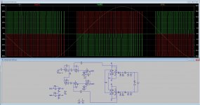
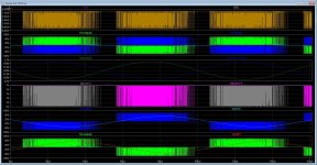
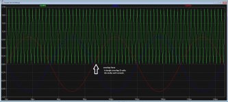
An externally hosted image should be here but it was not working when we last tested it.
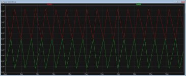
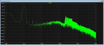
? Neglect "red graph" dis is not relevant.
We have created "sine using Vcc, 0V and -Vcc,.. this should be BD mosulation.
I would say we need two self oscilating clas D amps and some logic.
We have sine audio input. "positive half period of sine" we feed to one amplifier which is supply by "VCC VS 0V " (not Vcc vs -Vcc), and other half of sine we feed to another class D self oscilating amp which is supplied using 0V and - Vcc..
Output is difference between this two amps ?!
Kees, I have other idea, I wonder can three of such UCD-s be used for 3 phase motor control, but without any mictroncontroller or logic.
Self oscilating loop using current feedback what will vary frequency and voltage of 3 phase sine generator accordingly.
hi grizlek, you did ask about motor, here, but not a problem, motor needs really a cpu, not self oscillating.
Yes the loop did oscillate, I did however get it from internet, it is not mine idea, however, it is not a good way I think except when it can be synchronized, here I did.
But BD modulation is 3 level modulation , and you manage to make it working using self oscillating loop ? !!
I mean 3 level for audio single output, not 3 phase motor control ..
But is not this 3 level modulation ?An externally hosted image should be here but it was not working when we last tested it.
? Neglect "red graph" dis is not relevant.
We have created "sine using Vcc, 0V and -Vcc,.. this should be BD mosulation.
I would say we need two self oscilating clas D amps and some logic.
We have sine audio input. "positive half period of sine" we feed to one amplifier which is supply by "VCC VS 0V " (not Vcc vs -Vcc), and other half of sine we feed to another class D self oscilating amp which is supplied using 0V and - Vcc..
Output is difference between this two amps ?!
I can not open the pic, but waht you say is right, the modulation is two halves like in class ab amps, but as I did try, it swings between pus and minus vcc, you say we need two parts one with only negative supply and one only positive supply, I did not try yet because I did see nowhere this is needed, I did see offsets with or modulation or triangle signal.
I did look at the crown amp, there she do use buck converters as audio amps, but I think thermal runaway will be included again, or we have just a switching class b amp, not good, real BD modulation do the same, we need to inject very small pulses, of this will runaway I do not now. Normal class D where there is dead time, is in fact a little the same, nature do not let play with it without there rules.
thanks for anwer, I go later try the supply like you did mention, but in all examples there are symetrical supplies or even just a single supply with offsets making voltage VCC devide by two.
Hi
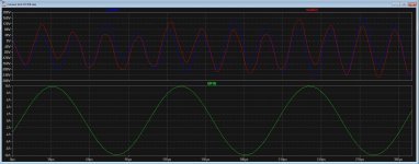
I did try, it did work but miss half of the sinus signal, the positive one is gone.
it is done with offsets of the signals some way, the self oscillating I do not sure that it will work.
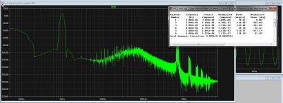
But sometimes I get really low distortions, like last pic, with some low pass filters tuned different..
regards
I did try, it did work but miss half of the sinus signal, the positive one is gone.
it is done with offsets of the signals some way, the self oscillating I do not sure that it will work.
But sometimes I get really low distortions, like last pic, with some low pass filters tuned different..
regards
Attachments
Last edited:
But BD modulation is 3 level modulation , and you manage to make it working using self oscillating loop ? !!
I mean 3 level for audio single output, not 3 phase motor control ..
But is not this 3 level modulation ?An externally hosted image should be here but it was not working when we last tested it.
? Neglect "red graph" dis is not relevant.
We have created "sine using Vcc, 0V and -Vcc,.. this should be BD mosulation.
I would say we need two self oscilating clas D amps and some logic.
We have sine audio input. "positive half period of sine" we feed to one amplifier which is supply by "VCC VS 0V " (not Vcc vs -Vcc), and other half of sine we feed to another class D self oscilating amp which is supplied using 0V and - Vcc..
Output is difference between this two amps ?!
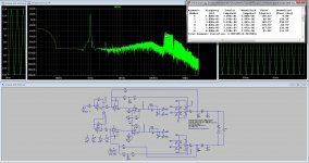
If I read the books wel, but also see the schematic of the K1 K1 crown amps who is in fact a BD modulator but she uses two buck converter outputs, who is by the way tricky, nice to see the resistor banks who prevent thermal runaway when she do overlap it.
I drawn the triangle generator and she do use there a adjust with a pot for overlap, in other papers she do use triangle with +vcc and -vcc and two opposite input audio signals who give then the two signals, a lot is unclear there.
Do seem that I did get a low hd amp, no DB, did not work well, but some other form. See pics of output amp setup. -100dB distortion
regards
Attachments
We have sine audio input. "positive half period of sine" we feed to one amplifier which is supply by "VCC VS 0V " (not Vcc vs -Vcc), and other half of sine we feed to another class D self oscilating amp which is supplied using 0V and - Vcc..
I do not now if the comparators do like a -vcc voltage to let them work properly.
has some done here, two triangles do work, can overlap then also for idle current.
Need to make two triangles not inverted, but needs negative and positive part.
Ive hobbie, learn a lot of it, because class d is quite new for me.
regards
Need to make two triangles not inverted, but needs negative and positive part.
Ive hobbie, learn a lot of it, because class d is quite new for me.
regards
Attachments
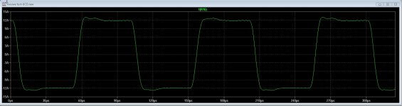
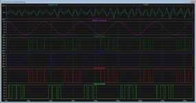
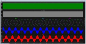
here you see the triangle and the input signals, for the crown amp, she use just the two halves of the audio signal, ignore the other half or just amplifie half, but this can give distortions.
or and this I like more is use two triangles one in opposite fase to make it with one full audio signal and not halves.
overlapping it and you can adjust the coil current like a normal amp.
For the output, I get a very nice current output but not a voltage output these are pretty distorted, it looks like a lot of common mode stuff, see last pic.
regards
Attachments
Overlap is good because low frequency audio requires the most power, and thus class D might be most appealing. Also, crossover distortion for low frequency audio is potentially more subjectively bad because the lower frequency means the signal is in the crossover region longer.
- Home
- Amplifiers
- Class D
- What Class-D amp give best sound?