Hello guy, I found new TPA3255 amp on ali. What do you think about?
TPA3255 Dual channel Class D digital power amplifier board DC24 48v high power output 300W + 300W|Amplifier| - AliExpress
It its very cheap. I don't know if I should buy one for test^^
TPA3255 Dual channel Class D digital power amplifier board DC24 48v high power output 300W + 300W|Amplifier| - AliExpress
It its very cheap. I don't know if I should buy one for test^^
Hi
I have BRZHIFI TPA3255 amplifier and i used it a while ....
I have an most Important Problem ..
the right channel is 1-2dB less than the left channel
So i measured a little.
What do i have now...
12v - LM2575HVS 470uH 220/25V ( measured 180mV ripple with 50khz Spikes - switching frequency )
TPA3255 AVCC ist only a simple 4R7 100nF circruit
(measured 170mV ripple with 50khz spikes )
OPV supply : Same Like AVCC .. but 47R with 100uF/25V
(Measured 150mV ripple with Same 50khz Spikes )
And also Vopv/2 with Lots of ripple and Spikes
Output of amplifier ~ 750mVpp @460khz in every Output
Also you can See the 50khz switching Spike ...
So i changed a bit some parts ..
Unknown SMD Caps removed and soldered some new nichicon/Panasonic Caps
Removed 470uH inductor and use a 220uF shielded Würth Type
This new 12V hast a ripple of 40mV ...without any Spikes.
.. 40mV ist good for this Type of regulator IMHO
Added a 1000uH + 470uF Filter top Feed the analog Part.
And added some 100uF Caps ...
Here you can read 20mV ripple...
On Output now you can measure 250mV ripple @450khz
Why ist this circruit Not Standard ???
Then ... Output filter..
Inductor Look OK
But the Cap IS a simple X5 or x7 Type
It should have 1uF ... I desolderd it and measure 0,8uF ..
@48V ... Hmmm with luck 0,5uF
So i ordered new 1uF wima types
And also OPA1656 ...
Now i would switch to my Problem...
I added parts for PFFB. But If i Connect to the Input(after OPV resistor ) the the AMP goes Info fail state
The Output inductors make a loud chirp noise ..
Somebody an Idea why???
As i See,. One OPV is for treble and Bass , the Output goes into TPA chA . The Other OPV invert this Signal and is connected to chB of TPA .
Can this be a Problem to use PFFB ?
Problem solved ^^
LM2575HV was soldered ... it should Work with 48V
But Diode is a 40v Type . 1N5819
New Power supply .. 45V
Manufacturerof amplifier Said 24-48V !!! ... So i use 45V ....
Lm2575 Power supply killed
TPA Chip killed
Both 3,3V LDOs killed
PCM5102 killed
QCC5125 Bluetooth Module killed
Last edited:
Hello,
I bought this board to use as external amp for my avr.
The thing is, it looks like the input has very low sensitivity.
Any one experienced this kind of low output at the same input level.
Other question, this board has a very light hiss which I can ear if I am very close to the speakers. This might be some kind of PSU issue? I'm using an old hp laptop PSU with 19v and 7amp.
Are the 2 "problems" related to the PSU?
The board I have is this one:
TPA3255 2.0 Class D digital power amplifier board high power 300W+300W|Amplifier| - AliExpress
BRZHIFI TPA3255 amplifier
A good day to all!
I have a BRZFiHi TPA3255 amplifier and I encountered a rather curious problem which I couldn't figure out.
The amp has 3 nos. opamps in it and they are fitted with JRC5532. I presume 2 are for the BTL config and 1 is for gain stage.
Since I have 4 nos. LM4562, I wanted to see if there would be any noticable difference if I replace them.
Replacing all the 5532 with 4562, there was no ouput to the spkrs.
I thought it could be a faulty 4562. So I randomly removed and fitted back 2 5532 and it was alive again.
To cut the long story short, after fiddling with different combi of opamps at different DIP8 slots, I discovered that I could use ONLY TWO 4562 at any one time. If I use, say, a LM833 as the third opamp, I can put it into any of the 3 DIP8 slots and it will work just fine. Replaced with a 3rd 4562 and it will be silent.
Any idea what could be the issue?
Last edited:
The 4562's have a slightly higher current draw than the 5532. The 4562s also have a wider bandwidth 55Mhz vs 10 Mhz. I tried to swap out 5532s in a SMSL dac and I could not do to the slightly higher current draw of the 4562s. If you have a DMM measure the supply voltages on pins 4 and 8 and compare. Also check the output pins on pin 1 and 6. It may give you a clue.
The 4562's have a slightly higher current draw than the 5532. The 4562s also have a wider bandwidth 55Mhz vs 10 Mhz. I tried to swap out 5532s in a SMSL dac and I could not do to the slightly higher current draw of the 4562s. If you have a DMM measure the supply voltages on pins 4 and 8 and compare. Also check the output pins on pin 1 and 6. It may give you a clue.
thank you for the enlightenment.
will try to measure the pins later. need to insulate my probes before poking at the components coz there are quite a number of bare metal smt caps around and I don't want to short anything if my probes slip

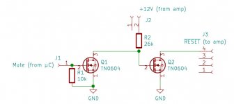
Simple circuit to avoid pops with the EAUMT-0260
Couldn't find this in the discussion about the 3e Audio board, so I thought this might be of use for someone. It is a simple interface between a µC and the amp which ensures mute while the µC is down while the amp is (already/still) up.
Cheers
Couldn't find this in the discussion about the 3e Audio board, so I thought this might be of use for someone. It is a simple interface between a µC and the amp which ensures mute while the µC is down while the amp is (already/still) up.
Cheers
Attachments
For example something like this:
Zasilacz impulsowy 36V 360W 10A CNC LED Reprap - Sklep internetowy AGD i RTV - Allegro.pl
I read in the descriptions here that a power supply with two outputs is not suitable. How to understand?
Zasilacz impulsowy 36V 360W 10A CNC LED Reprap - Sklep internetowy AGD i RTV - Allegro.pl
I read in the descriptions here that a power supply with two outputs is not suitable. How to understand?
For example something like this:
Zasilacz impulsowy 36V 360W 10A CNC LED Reprap - Sklep internetowy AGD i RTV - Allegro.pl
I read in the descriptions here that a power supply with two outputs is not suitable. How to understand?
It is an SMSP with a single output. Very correct.
- Home
- Amplifiers
- Class D
- TPA3255 - all about DIY, Discussion, Design etc