I can do so later. But do not expect any really news - my prototypes perform similar to the TI-EVM and there is not so much I can do about that. Instead of squeezing the last zero out of THD numbers I focus on an extra power management that enable battery operation and suppresses popping sound on power up / down using a microprocessor. I can add some postfilterfeedback also - but in a different way than TI do propose. This will be my power building block of high-efficient mobile instrument amps in the ballpark of 30~100W mono.
Did you try increasing the gain before TPA3255 ?
I did. This works provided your op-amp is capable to deliver the high audio level at really low THD. But I am not intrigued to invest here for squeezing some 5dB lower THD figures, it is not worth the effort imho.Did you try increasing the gain before TPA3255 ?
Does changing the op amps really improve sound quality or does it change the sound? Is this measurable?
You will hear a difference switching OP amps (in my case OPA1656, Aiyima TPA3251 Tilear 2.1). It is certainly measurable and this is why I asked Rhing to send the updated version to Audio Science review but still waiting for his feedback.... This would be the best way to check improvement.
I made some "human" test with Burson Audio V5I / OPA1656 / OPA627 / OPA1622 / OPA1612 / OPA MUSE01, they all sound differently. I would say that switching OP amps it is like changing Tubes : You can have surprising results when listening
Last edited:
I have speakers that can be bi-wired (a metal strap connecting the low pass section of the crossover to the high pass). With the strap removed, and if there were a way to access the point just before the LC filter's inductor, could one bypass the LC filter and wire straight to the low pass section of the crossover? It seems like the low pass current would be passing through far fewer components (an audio improvement?), and the high pass current through the LC filter would be greatly reduced.
Apologies for the rough drawing.
Mike

Apologies for the rough drawing.
Mike
What is the length of the wires? From Amp to speaker?
Let's say 10 ft 12 awg, or 20 ft from OUT_A to OUT_B.
the inductance of the speaker will ruin this idea
I assumed the inductive load of the low pass crossover/driver would be in parallel with the capacitive load of the high pass crossover/driver, as far as the TPA3255 output pins are concerned.
Thanks for the responses.
Mike
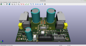
Meanwhile I had some ideas for improvements that ended in additional iterations of the TPA325x-PBTL pcb-design. Actually that is the news:
+12V Sync-buck-regulator extended to “flybuck” providing +-12V symm supply for op-amps.
10pin IDC-connector added to connect via ribbon cable a new control pcb providing 4 operating status LEDs and another 10pin port for diagnostic measurments.
Replacing output inductors by latest Würth HIDE-series with small footprint.
PCB dimensions shrinked from 100x75mm down to 100x62mm.
Attachments
I was able to improve EVM of 6.67Khz/10W/4R (non PFFB) from 0.012% to 0.005%
With PFFB (while not tested) I would expect it to be 0.0025%, Our goal is to make it around 0.001 % at a max
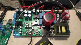
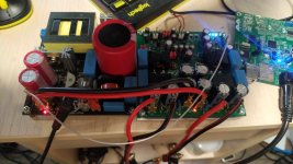
What I did , is tryed over 20 inductors and ended up making a custom one. As you can see inductor influences distortion by quite a good amount .
With PFFB (while not tested) I would expect it to be 0.0025%, Our goal is to make it around 0.001 % at a max
What I did , is tryed over 20 inductors and ended up making a custom one. As you can see inductor influences distortion by quite a good amount .
Meanwhile I had some ideas for improvements that ended in additional iterations of the TPA325x-PBTL pcb-design. Actually that is the news:
+12V Sync-buck-regulator extended to “flybuck” providing +-12V symm supply for op-amps.
10pin IDC-connector added to connect via ribbon cable a new control pcb providing 4 operating status LEDs and another 10pin port for diagnostic measurments.
Replacing output inductors by latest Würth HIDE-series with small footprint.
PCB dimensions shrinked from 100x75mm down to 100x62mm.
IN PBTL mode according to datasheet support 2-4 ohm. what about 8 ohm?
I was able to improve EVM of 6.67Khz/10W/4R (non PFFB) from 0.012% to 0.005%
With PFFB (while not tested) I would expect it to be 0.0025%, Our goal is to make it around 0.001 % at a max
What I did , is tryed over 20 inductors and ended up making a custom one. As you can see inductor influences distortion by quite a good amount .
Can you share custom inductor details. I want to try on my board.
There is no problem in downgrading from 2-4 Ohm to 8 Ohm.IN PBTL mode according to datasheet support 2-4 ohm. what about 8 ohm?
Yes, DOWNgrading, as the current flow drops to 1/2~1/4.
Power dissipation drops as well so a small heatsink will do.
And with its small heat sink my design is suitable for 8 ohms and will overheat at 2-4 ohms.
Last edited:
I am surprised because I can confirm you that I have that "pop" sound when I switch on the amplifier.... But I found a way to prevent the amp from "poping" via the Linear PSU )
hi. can you please share how you solved the popping noise through your linear power supply. thanks
- Home
- Amplifiers
- Class D
- TPA3255 - all about DIY, Discussion, Design etc