Interesting.. If that is performing without hiss I'd be really impressed. They stated they use only 50V caps so I wouldnt run 48V at all on that board.
Are you looking for a 4 channels board ? or 2.0 ?
So let us see who will get his samples first
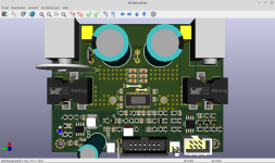
My PCB today sent to me
Sorry, no.Are you familiar with Attiny programming and flashing?
For my DSP firmware writed my friend.
Not looking for new board at the moment. I'm running two 3e Tpa3255s in my main amp. One stereo card for left channel and one for right channel. Two Meanwell psus drives them. I use them for biamping, and this way I have one separate choke pair for each speaker driver. It really sounds clean at high levels!. Some amps cant handle the Xtz 99.26 MK2 at very high listening levels, but the 3e boards drives them with ease. I bypassed the opamps onboard and I use a very hot signal from the es9038 dac I just built from the guide on this forum. I swapped out some of the input electrolytics for smaller film caps to create a 1.order 200Hz higpass filter for the speaker's woofers. That allowed the speaker to play much louder and cleanly. Pairing them with higher XO subs also got easier.
The Aiyima 3255 I just finished modding was for a friend who was looking for something small and powerful. I ended up installing a small Gelid 12v 40mm fan inside the amp cabinet with input and output holes in the upper half. Its beeing run with at 48V step down and a temperature controller. The 48V step down regulators available on ebay is tiny!
I skipped the weak 5mm plug it came with and hard soldered 4mm^2 wires straight onto the pcb for minimum resistance into the psu. Wires were shortened to 12cm going into the Meanwell. Since the amp has too little capacitance I didnt want to create more ripple by utilising that poor 5mm plug it came with. I paired that with an 800W Meanwell psu with a pretty beefy output capacitance. I know my friend is going to push that system hard so its going to be interesting to see how that board will handle beeing run at max for some 3-4 hours straight often. I adjusted the psu down to 45V to give the stock 50V caps a chance ^^.
If some better cheap Tpa3255 designs comes along its always interesting to test them out Daniboun. That 4 channel clone could be a killer amp with all expected shortcomings fixed hehe. Many reviewers on YT is finally admitting that class D has become very good and I think bi or tri amping with DSP is going to a huge deal the next years.
Not looking for new board at the moment. I'm running two 3e Tpa3255s in my main amp. One stereo card for left channel and one for right channel. Two Meanwell psus drives them. .............
If some better cheap Tpa3255 designs comes along its always interesting to test them out Daniboun. That 4 channel clone could be a killer amp with all expected shortcomings fixed hehe. Many reviewers on YT is finally admitting that class D has become very good and I think bi or tri amping with DSP is going to a huge deal the next years.
Hi,
Can you show your modified board ? Seems to be a really nice mod !
There are now lots of new TPA32XX boards, everyone now knows my enthusiasm on this forum but unfortunately I am often asked to measure the performance of what I discover or buy ...I am therefore not in the best position I think to meet these expectations. I trust my ears and how I feel when I listen to my HD playlist.
I think we should wait for Rhing's return regarding the Audio Science Review. I put him in contact with Amirm who accepted to test the Aiyima TPA3251.
It will be the best basis we will have for realizing if those little Chinese amps are really good. I will review soon a new high end TPA32XX based on 360 Customs design.
Last edited:
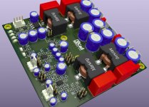
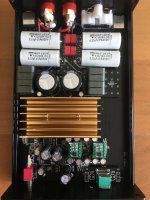
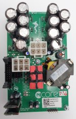
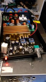
Finally modded the AIYIMA. I wanted everything to fit in the case, that's why I proceeded with this board.
Wruth Inductors
Vishay MKPs
Wima FKPs
Paired a small cap with the power cap
The end product sounds great, the OPA1656 really adds the sparkle. Unfortunately, there's some leakage with my DIP8 board so I had to stick with the OPA1622 for now. It's probably due to the flux, cleaned it with 70% alcohol, hope it works after it's dry.
I need to look for new caps as the Panasonic FS 1000uf caps are too tall by a few mm so now I can't close my case.
I connected the amp without a source and turned the volume to the max, no hissing, not sure if this was the case before modifications. With a source, the hissing only starts at half volume, but it's probably due to the source.
Attachments
Last edited:
Finally modded the AIYIMA. I wanted everything to fit in the case, that's why I proceeded with this board.
Wruth Inductors
Vishay MKPs
Wima FKPs
Paired a small cap with the power cap
The end product sounds great, the OPA1656 really adds the sparkle. Unfortunately, there's some leakage with my DIP8 board so I had to stick with the OPA1622 for now. It's probably due to the flux, cleaned it with 70% alcohol, hope it works after it's dry.
I need to look for new caps as the Panasonic FS 1000uf caps are too tall by a few mm so now I can't close my case.
I connected the amp without a source and turned the volume to the max, no hissing, not sure if this was the case before modifications. With a source, the hissing only starts at half volume, but it's probably due to the source.
What is the board you used for all the components. Do you have some more photos of the upgrade process ??
Can you explain what the new components replaced ?
Did replacing the output filter make a noticeable difference ?
There only a small amount of Hiss with the standard product if you put your ear right next to the speaker - Position of volume control makes no difference.
Many thanks
James.
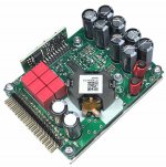
Very large size output filter capacitors, Bruno Putzeys recommends using the smallest possible size.
B32652A3684J000 TDK Electronics Inc. | Capacitors | DigiKey
B32652A3684J000 TDK Electronics Inc. | Capacitors | DigiKey
Last edited:
Very large size output filter capacitors, Bruno Putzeys recommends using the smallest possible size.
B32652A3684J000 TDK Electronics Inc. | Capacitors | DigiKey
Hi Dr Mord
Can you expand on this or give us a link to Bruno Putzeys recomendations document ?
See UcD, nCore, Purifi - all output caps small size
Attachments
Last edited:
Hi Dr Mord
Can you expand on this or give us a link to Bruno Putzeys recomendations document ?
It's not really about small size, although that is a physical side effect...
You're looking for extremely low series inductance (ESL) in this path, and capacitors with long leads, and physically large bodies will have significantly higher series inductance than a small capacitor with very short leads.
Ideally, you want COG/NPO surface mount caps and you want to use planes for the output and ground. This gives the lowest possible series inductance while achieving the desired capacitance.
Any inductance in this path will prevent the filter from working correctly (presents a high impedance to the high frequency switching fundamental and harmonics) and that means those high frequencies make their way onto your speaker wires where they will be radiated out into space instead of being shunted back to the GND plane. This could manifest as increased EMI or possibly even increased noise at the output.
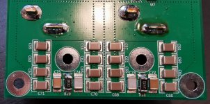
drMordor is absolutely correct though... those are not the correct caps for this application and are causing more harm than good. The correct way to do this can be seen in the attached image.
Luckily this is easy to do as a DIY mod as you just need to locate the output terminal of the output inductor, scrape off the surrounding solder mask (assuming there's a GND plane) and solder the SMD caps directly to the terminal or along the output trace to GND.
Regards,
Owen
Attachments
It's not really about small size, although that is a physical side effect...
You're looking for extremely low series inductance (ESL) in this path, and capacitors with long leads, and physically large bodies will have significantly higher series inductance than a small capacitor with very short leads.
Ideally, you want COG/NPO surface mount caps and you want to use planes for the output and ground. This gives the lowest possible series inductance while achieving the desired capacitance.
Any inductance in this path will prevent the filter from working correctly (presents a high impedance to the high frequency switching fundamental and harmonics) and that means those high frequencies make their way onto your speaker wires where they will be radiated out into space instead of being shunted back to the GND plane. This could manifest as increased EMI or possibly even increased noise at the output.
drMordor is absolutely correct though... those are not the correct caps for this application and are causing more harm than good. The correct way to do this can be seen in the attached image.
Luckily this is easy to do as a DIY mod as you just need to locate the output terminal of the output inductor, scrape off the surrounding solder mask (assuming there's a GND plane) and solder the SMD caps directly to the terminal or along the output trace to GND.
Regards,
Owen
Many thanks Owen.
Looks as if your example was specifically designed for SMD devices.
I was just surprised that LWJ5 had obviously gone to great lengths to use the best possible components on a special daughter board but I wasn't sure if this would result in any benefits.
Some other people have tried just upgrading the Output Filter with the TI EVM type Inductors (Coilcraft) and just quality Wima Capacitors. I still haven't seen any reports that this resulted in any real benefits over the originally installed Chinese choices.
Other than replacing the Op-Amps with OPA1656 ones I have yet to touch the rest of the components as I don't see anyone reporting any great gains with either of the Aiyima A04 and A07 TPA325x based Amplifiers.
I feel the TPA3251 based A04 maybe sounds better in the Bass than the TPA3255 A07 model as it has 3 x the Capacity on the main Supply Capacitors (2,000uF v 6,000uF) as everything else is equal.
For domestic use it also seems reasonable to keep the Supply Voltage at 30 Volts rather than try and drive the TPA3255 at the full 48 Volts.
Not seen discussed anywhere, but as the basic technology used in a digital amplifier is an ADC on the Input and a Filter on the Output shouldn't the quality of the output and dynamic range depend on the magnitude of the input signal ?? IE. if you you are only using the bottom 10% of the range of the ADC aren't you missing out on something.
Not sure I have explained myself very well but hopefully you will get the basic idea
James.
Hi James,
A few interesting topics here, and one really neat one I will attach some measurements for.
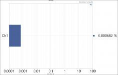
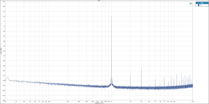
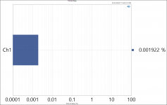
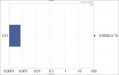
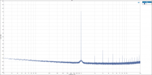
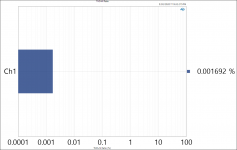
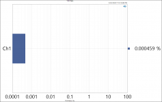
I'm not sure how common this knowledge is, but I noticed and measured something interesting while qualifying my board. Both output noise and THD increase with power supply voltage. It's not a huge amount, but it's easily measurable and repeatable. So, if you don't need the maximum power output (or more specifically maximum output voltage) then you are indeed better off using a lower voltage supply.
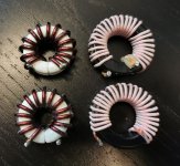
The output filter is likely the lowest hanging fruit for upgrades as long as you pick the correct parts. The table I've seen published here a few times is a superb resource for that. You want to choose an inductor with the flattest possible L vs I curve as any change in inductance with current will result in increased distortion. Using PFFB certainly helps compensate for this, but you want the best inductors you can get regardless of PFFB. You also need to make sure you pick a part that does not saturate anywhere near the current levels you will be using it at. There's an awesome paper from Ferroxcube on this topic from quite a while ago:
https://elnamagnetics.com/wp-conten...roxcube-Documents/Class_D_audio_amplifier.pdf
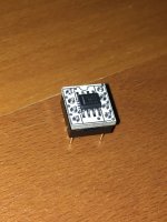
EDIT - Added a picture below of some hand-wound ferroxcube gapped ferrite toroids. I managed to get 14 turns of 2mm enamel copper wire on there... but my fingers hurt for days after
It's a common misunderstanding that the D in "Class D" refers to "digital" but these are not digital amplifiers at all, and they contain no ADC. They operate entirely in the analog domain.
There's a diagram on page 4 (Figure 1) in the above paper which might help with the understanding. The input of the amplifier is fed into a modulator which converts the input analog signal to an analog PWM signal. This is not an ADC as the output is not in binary (not digital), but simply a pulse width modulated version of the input. This PWM signal is then fed to the gates of the output stage (with appropriate dead time) and an amplified (higher voltage/current) version of that same signal appears at the output of the amplifier. This PWM signal is then fed into the output filter (L-C) where it is demodulated back to something that resembles the original input. It should be noted that this process is distinctively different from an A/D and D/A process. Hopefully this helps with your question. Below is a great paper on the basics of how a class D amplifier works and how it differs from more traditional linear class A or AB designs:
https://www.infineon.com/dgdl/an-1071.pdf?fileId=5546d462533600a40153559538eb0ff1
Finally, attached below are the measurements at different supply voltage levels. Images are labelled appropriately.
Regards,
Owen
A few interesting topics here, and one really neat one I will attach some measurements for.
For domestic use it also seems reasonable to keep the Supply Voltage at 30 Volts rather than try and drive the TPA3255 at the full 48 Volts.
I'm not sure how common this knowledge is, but I noticed and measured something interesting while qualifying my board. Both output noise and THD increase with power supply voltage. It's not a huge amount, but it's easily measurable and repeatable. So, if you don't need the maximum power output (or more specifically maximum output voltage) then you are indeed better off using a lower voltage supply.
Some other people have tried just upgrading the Output Filter with the TI EVM type Inductors (Coilcraft) and just quality Wima Capacitors. I still haven't seen any reports that this resulted in any real benefits over the originally installed Chinese choices.
The output filter is likely the lowest hanging fruit for upgrades as long as you pick the correct parts. The table I've seen published here a few times is a superb resource for that. You want to choose an inductor with the flattest possible L vs I curve as any change in inductance with current will result in increased distortion. Using PFFB certainly helps compensate for this, but you want the best inductors you can get regardless of PFFB. You also need to make sure you pick a part that does not saturate anywhere near the current levels you will be using it at. There's an awesome paper from Ferroxcube on this topic from quite a while ago:
https://elnamagnetics.com/wp-conten...roxcube-Documents/Class_D_audio_amplifier.pdf
EDIT - Added a picture below of some hand-wound ferroxcube gapped ferrite toroids. I managed to get 14 turns of 2mm enamel copper wire on there... but my fingers hurt for days after
Not seen discussed anywhere, but as the basic technology used in a digital amplifier is an ADC on the Input and a Filter on the Output shouldn't the quality of the output and dynamic range depend on the magnitude of the input signal ?? IE. if you you are only using the bottom 10% of the range of the ADC aren't you missing out on something.
It's a common misunderstanding that the D in "Class D" refers to "digital" but these are not digital amplifiers at all, and they contain no ADC. They operate entirely in the analog domain.
There's a diagram on page 4 (Figure 1) in the above paper which might help with the understanding. The input of the amplifier is fed into a modulator which converts the input analog signal to an analog PWM signal. This is not an ADC as the output is not in binary (not digital), but simply a pulse width modulated version of the input. This PWM signal is then fed to the gates of the output stage (with appropriate dead time) and an amplified (higher voltage/current) version of that same signal appears at the output of the amplifier. This PWM signal is then fed into the output filter (L-C) where it is demodulated back to something that resembles the original input. It should be noted that this process is distinctively different from an A/D and D/A process. Hopefully this helps with your question. Below is a great paper on the basics of how a class D amplifier works and how it differs from more traditional linear class A or AB designs:
https://www.infineon.com/dgdl/an-1071.pdf?fileId=5546d462533600a40153559538eb0ff1
Finally, attached below are the measurements at different supply voltage levels. Images are labelled appropriately.
Regards,
Owen
Attachments
-
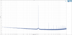 FFT 55P8V.png108.3 KB · Views: 170
 -
 THD+N Ratio 55P8V.PNG73.9 KB · Views: 120
 -
 THD Ratio 55P8V.PNG72 KB · Views: 152
 -
 FFT 51V.png110.4 KB · Views: 161
 -
 THD+N Ratio 51V.PNG73.6 KB · Views: 130
 -
 THD Ratio 51V.png71.9 KB · Views: 153
 -
 FFT 28V.PNG108.6 KB · Views: 157
 -
 THD+N Ratio 28V.PNG73.9 KB · Views: 162
 -
 THD Ratio 28V.PNG72 KB · Views: 269
 -
 FerroxCube Inductors.jpg648.1 KB · Views: 229
Last edited:
All in all we can conclude that distortion of TPA325x designs is dominated by the output inductors so it is a good idea to look for the best ones. There exists a TI appnote comparing measured THD of different chokes confirming this.
Did similar measurements with readily wound inductors and ended up with gapped ferrite pot cores like WE744363xxxx
Did similar measurements with readily wound inductors and ended up with gapped ferrite pot cores like WE744363xxxx
Last edited:
Ideally, you want COG/NPO surface mount caps and you want to use planes for the output and ground. This gives the lowest possible series inductance while achieving the desired capacitance.
Not using C0G/NP0 in the output gives some nice effects due to DC-bias when using i.e. X5R/X7R. As capacitance is a function of voltage across the capacitors the filter is quite "variable" at different levels of output signal.

I wouldn't call this an issue at all as long as your desired filter frequencies are way out of the audio-band. As long as you don't fight EMI-regulations...
Regarding ESL and the likes, all fine for measuring and down-hunting THD-plots, but ever checked again with real speaker-load at an 3-5m long cable in between?
Just saying.
Very large size output filter capacitors, Bruno Putzeys recommends using the smallest possible size.
B32652A3684J000 TDK Electronics Inc. | Capacitors | DigiKey
I'd guess the main reason for this is to not having some nice antennas in your outputs. It also depends on stacked or wound foil-layout in the cap + orientation with respect to the magnetic field of your inductors.
Last edited:
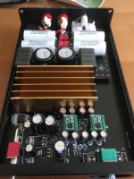
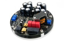
Daniboun I forgot to take a picture before I delivered the amp.. I only have a picture from half way in the mods.. Some of the visible caps mods you see in the picture didnt give any noticable effect unfortunately. But atleast you see the step down board and temperature board for the fan. I also only have my own ears to go by and very little measurement equipment at the moment. An oscilloscope would have been very tracking down the source of the hiss.
Attachments
I wouldn't call this an issue at all as long as your desired filter frequencies are way out of the audio-band. As long as you don't fight EMI-regulations...
Regarding ESL and the likes, all fine for measuring and down-hunting THD-plots, but ever checked again with real speaker-load at an 3-5m long cable in between?
Just saying.
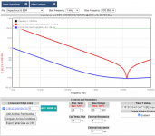
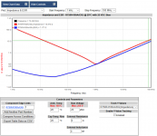
I'm not suggesting the capacitors have any audible effect in the audio band at all. The output LC filter is present to remove the 450kHz switching fundamental and all of its harmonics. The capacitor in particular should not have any effect on THD in the passband at all (assuming it's the correct value), regardless of a real speaker load or a resistive dummy load.
The issue here is EMI... that's the purpose of the filter. It's the only reason it's there at all. The speaker certainly cannot reproduce 450kHz, and even if it could, we could not hear it... so why have a filter at all? It's for EMI.
I'm not suggesting that every home built amp should be certified to meet EMI/EMC, but it's certainly in the best interest of the user to ensure that they aren't polluting their home with RF interference. We rely heavily on Wifi, 3G/4G/5G cell band, Bluetooth, GPS, AM/FM reception, and an abundance of other wireless devices in our lives. If the amplifier you just built has reduced your Wifi throughput by 50% because you decided to to use massive foil capacitors fly-wired onto the output LC filter hoping for better sound, then all I'm suggesting is that you choose a capacitor fit for purpose. In this case, surface mount COG/NPO caps are the best fit for the purpose. The only downside is that they are expensive, and you need to use multiples to get to 1uF.
Please see the two attached plots and let me know which you would prefer for filtering a 450kHz fundamental and its harmonics.
Regards,
Owen
Attachments
- Home
- Amplifiers
- Class D
- TPA3255 - all about DIY, Discussion, Design etc