Sorry, how do you ever get 80Vpp from a single voltage, bridged amp that runs on 48V?
Can you calculate how many watt´s 48Vpp are at a 4 ohm load? Should be roughly 300watt at acceptable clipping.
If your amp is powered by 51 Volt and the voltage has to travel over some diode /transistor, how many volt do you lose at each one? This is not a mechanical switch, but a semi conductor amp.
How can you be surprised, when you only see 48V at clipping? You do not have a super conductor amp as far as I know?
Just as a reminder, for power calculation of such an single voltage power supply, bridged amp, you divide Vpp by 1.4 then multiply the result by it self and divide by the load resistor. If it was not bridged, power would be 1/4 single ended.
Only if your amp (theoretical) burns to a short cut from input to output you can see the full voltage. Then you have 51V and, at 4 ohms will burn 650 watt´s, if you PS can deliver 12.75 A.
xrk971
perhaps yours is not in Bridged mode or one or more of the 4 SE channels is not working. You have built many amplifiers and I know you measured across the outputs and not between one output and ground. I have the same board and it easily matches the rated power specs.
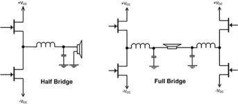
for those not familiar with bridged mode, the effective output voltage is doubled and the resulting output power is squared. So a bridged amplifier with a single 50volt rail will output a little less than 100voltPP. A bridged amplifier with + - 50volt rails will output a little less than 200volt PP. Providing low losses and a very stiff regulated power supply.
perhaps yours is not in Bridged mode or one or more of the 4 SE channels is not working. You have built many amplifiers and I know you measured across the outputs and not between one output and ground. I have the same board and it easily matches the rated power specs.
for those not familiar with bridged mode, the effective output voltage is doubled and the resulting output power is squared. So a bridged amplifier with a single 50volt rail will output a little less than 100voltPP. A bridged amplifier with + - 50volt rails will output a little less than 200volt PP. Providing low losses and a very stiff regulated power supply.
xrk971
perhaps yours is not in Bridged mode or one or more of the 4 SE channels is not working. You have built many amplifiers and I know you measured across the outputs and not between one output and ground. I have the same board and it easily matches the rated power specs.
for those not familiar with bridged mode, the effective output voltage is doubled and the resulting output power is squared. So a bridged amplifier with a single 50volt rail will output a little less than 100voltPP. A bridged amplifier with + - 50volt rails will output a little less than 200volt PP. Providing low losses and a very stiff regulated power supply.
I supposed he measured from ground, because his results are exactly what you will get there.
The voltage rail can only be "switched" to one side of the voice coil at a time, so you only see 48 volt from ground. You will not see the double voltage the voice coil get´s.
The bridged amp is the same as two single ended amps serving half of the coils resistance, resulting in 4 times the power. Once doubled by two amps and a second doubling by halving the load resistor.
As I mentioned earlier in some related thread it is no good idea to measure (P)BTL against GND because THD relative to GND is one magnitude worse than measured diagonnally. For my knowledge XRK does it that way.
There seems to be substantial common mode THD that cancels out in full bridge.
And if you assume that one of both input channels is dead, you measure half of the output level.
There seems to be substantial common mode THD that cancels out in full bridge.
And if you assume that one of both input channels is dead, you measure half of the output level.
Last edited:
My board lightning two red diode and it is seems like normal since when i tried it work at 20v/6a brick psu one red light turned off and one channel off as well while increasing volume 50+% - just not enough power in brick and protection rurned off slave channel by high current fault imho.
Hi Antony
here is the board...sometimes i get 1 step forward and 2 steps back...but with the help if the community i learn something") ...and the sound is fine
...and the sound is fine
https://www.diyaudio.com/forums/class-d/309813-wrong-tpa3255-21.html#post5447118
chris
here is the board...sometimes i get 1 step forward and 2 steps back...but with the help if the community i learn something
...and the sound is finehttps://www.diyaudio.com/forums/class-d/309813-wrong-tpa3255-21.html#post5447118
chris
I supposed he measured from ground, because his results are exactly what you will get there.
The voltage rail can only be "switched" to one side of the voice coil at a time, so you only see 48 volt from ground. You will not see the double voltage the voice coil get´s.
The bridged amp is the same as two single ended amps serving half of the coils resistance, resulting in 4 times the power. Once doubled by two amps and a second doubling by halving the load resistor.
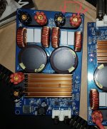
The Chinese amp is setup only as BTL. There is no GND terminal at the outputs. Here is an image of the same amp and where I measured.
I think the design is flawed because I bought two from two different vendors and they did the same thing. Both had error lights when they are working. Both could only output 48Vpp with 48V supply.
I might revisit it to see what’s going on. Perhaps the input opamps were not set up right and don’t drive a differential output? In which case, you don’t get bridged mode.
As I mentioned earlier in some related thread it is no good idea to measure (P)BTL against GND because THD relative to GND is one magnitude worse than measured diagonnally. For my knowledge XRK does it that way.
I think I measured the same way you measured using the similar symmetric voltage divider rig that you used. After Dr Mord showed me how you guys did it. Not relative to GND.
Attachments
Last edited:
How could a bridged amp deliver more Volts PP to a loudspeaker than the potential between the two power rails?
Think about it.
That’s what bridged mode does. Both ends of the output are “live” - they are out of phase by 180 and output can theoretically be double the single rail.
That’s what bridged mode does. Both ends of the output are “live” - they are out of phase by 180 and output can theoretically be double the single rail.
Yes, but only in a dual supply setup.
In a single supply setup, each output has the rail voltage as its maximum, and ground as its minimum, give or take some losses. So this is the maximum peak to peak voltage, the difference between the supply voltage and ground.
In a dual supply setup, it is basically the same: it is the difference between the two rail voltages, which defines the maximum peak to peak output voltage bridged. Since in unbridged mode the maximum pp is only half, that is, the difference between ground and one of the rails, bridging it doubles this distance and hence the peak to peak output voltage.
Last edited:
Yes, but only in a dual supply setup.
In a single supply setup, each output has the rail voltage as its maximum, and ground as its minimum, give or take some losses. So this is the maximum peak to peak voltage, the difference between the supply voltage and ground.
In a dual supply setup, it is basically the same: it is the difference between the two rail voltages, which defines the maximum peak to peak output voltage bridged. Since in unbridged mode the maximum pp is only half, that is, the difference between ground and one of the rails, bridging it doubles this distance and hence the peak to peak output voltage.
It is not possible to run a classD amp on a single supply line in unbridged mode.
I believe the discussion on the total rail voltage being the limit for the peak-to-peak output voltage includes a small misunderstanding. Evidently, the instantaneous output voltage cannot exceed the total rail voltage. But, as the output changes polarity for the following half-wave, the top of one half-period to the top of the following half-period can be up to twice the total rail voltage with BTL coupling. Both views are right but based on different assumptions.
I have managed to run a TDA8932 from a single supply line, in unbridged mode (SE mode). Ouput from one line only and a coupling capacitor to the negative rail as used with the "old" class AB amplifiers running from a single rail.
Last edited:
Vacufile, I believe you are mistaken. It doesn't matter if the amplifier is single supply voltage or dual supply voltage. In bridged mode the output voltage is doubled. Suppose you have two amplifiers you wish to bridge amp A and amp B. Let's say they both have a single rail supply of 48VDC. The output of each amplifier will be around the halfway point or about 24VDC. The difference between output A and output B is 0VDC. As you apply an input signal out put A will go towards the positive 48 vollt rail and out put B will go towards the ground 0 volt side. Now you have output A 48 volts more positive than out put B. When the input signal swings negative. Output A goes toward the 0 volt ground side and output B goes towards the 48 volt rail. Output A is now 48 volts negative in respect to output B. We now have an amp that can out put + - 48 volts.
A bridged amp is always made of two amps. Each single amp has a maximum output at given load.
If you look at what counts, the output in watt, it is exactly what you get if you leave the two amps separate, but half each amps load impedance. No need for double voltage!
The trick, why bridging amps is needed, you can not half a single speakers impedance without opening it up and modifying it´s voice coil!
If you had a speaker with a double voice coil´in series, you could open the series connection and put one amp to each single coil. No need to bridge the amps! Still same output as from a bridged amp at the single coil.
The misconception seems to be, some think only on the volts and not the ampere drawn of the amps. You can not bridge any amp, as it has to be able to deliver twice the ampere, too! So an amp you can bridge must always be able to run at 2 ohms, if you want to run it in a 4 ohm bridge.
Think of the amps as they where single battery cell´s. One got 1.5 volt, put in series, you get 3 volt.
Here, bridged, you only have one battery. So no way to get 3 volt out of a single cell!
If we double the available ampere from the single cell, we can connect 2 two times the halved load.
So to complete the picture, take two separate cells with half load each and connect them at positive and negative pole. Nothing will happen, the available power is 4 times the starting point. Open the + + and - - connection, again, still 4 times the power. Still 1.5 volt.
This remembers me of the discussion with some guy who could not see the benefit of a RCA line connection with two wires and a screen only connected at one side.
Last edited:
each half bridge output on this amplifier cant give more than 48v PP, it is impossible, you need two of those for 96v PP output swing wich is also impossible if he is shorting one half bridge output to ground with his oscilloscope.
no mistery and one side cant give 96v PP when other side is shorted to ground.
no mistery and one side cant give 96v PP when other side is shorted to ground.
Attachments
each half bridge output on this amplifier cant give more than 48v PP, it is impossible, you need two of those for 96v PP output swing wich is also impossible if he is shorting one half bridge output to ground with his oscilloscope.
no mistery and one side cant give 96v PP when other side is shorted to ground.
You are right because you consider the instantaneous voltage.
If you, on the other hand, look at the load voltage the way we have done it for decades (X-Y diagram: voltage vertical, time horizontal) you will have +48V (peak) for a positive half-wave followed by -48V (peak) for the following negative half-wave. +48V to -48V is 96V peak-to-peak in our traditional terminology.
The trick of the BTL coupling is that it moves the reference dynamically such that the outputs stay within the supply voltage span.
- Home
- Amplifiers
- Class D
- TPA3255 - all about DIY, Discussion, Design etc