As I don't like to remove the heat sink atm, I tried to measure if the resistors are still there but I am not able to. I got my EVM3255 this week so it should be fixed/updated.
The other fix for this (from ti topic) is a lot simpler and you won't have to remove the heat sink:
The other fix for this (from ti topic) is a lot simpler and you won't have to remove the heat sink:
About holding the reset pin on power up and down;
Would a DPST (double pole, single throw switch) as power switch and a $1delay module like this 'fix' this?
// Edit: I think a regular 3 pole on/off switch might work as well.
My idea is connecting the reset switch in off position and when switched to on, the relay switches the reset off a second later. When powering off the reset will be activated by the off position and the relay will switch back to hold the reset.

// And other thing that still is not clear to me; can I connect this and a preamp to the 12v pin header J32? Or can I but would it be better to connect them to a step down buck convertor?
Would a DPST (double pole, single throw switch) as power switch and a $1delay module like this 'fix' this?
// Edit: I think a regular 3 pole on/off switch might work as well.
My idea is connecting the reset switch in off position and when switched to on, the relay switches the reset off a second later. When powering off the reset will be activated by the off position and the relay will switch back to hold the reset.
// And other thing that still is not clear to me; can I connect this and a preamp to the 12v pin header J32? Or can I but would it be better to connect them to a step down buck convertor?
Last edited:
Hi Think -
I removed the heat sink - it is trivial, just two screws and goes back on easily so if you want to try should be pretty straight forward. You may be able to read the resistor values (R36, R52) but the writing is tiny - I measured with meter (9.9k ohms) to confirm what I thought the code was.
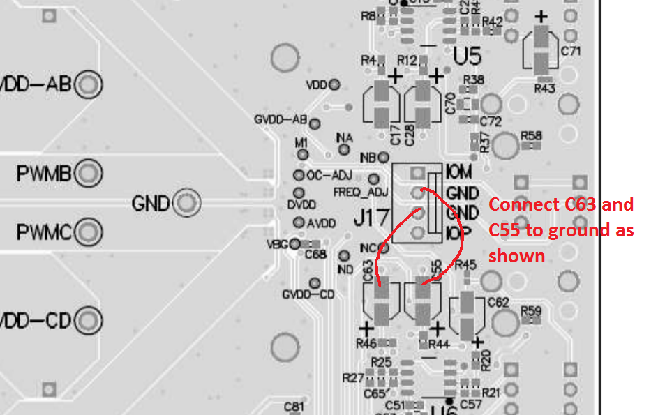
Yes, per your diagram, I was going to make a simple molex connection from jumper J17 with two wires to the capacitors (C55 and C63) to ground them - this would give me the option of grounding the pull down resistors vs leaving them in the native state simply but plugging / unplugging the molex connector into J17. These capacitors (C55 and C63) are on the bottom of the board so it is not necessary to remove the heat sink and they are a bit larger than resistors (R36, R52) so easier to make solder connection.
My question regarding the TI link with the TPA3255: Issue When Using PBTL Mode -
it is not clear to me if the issue only when he was testing PBTL mode at or near full power or ?
Cheers!
I removed the heat sink - it is trivial, just two screws and goes back on easily so if you want to try should be pretty straight forward. You may be able to read the resistor values (R36, R52) but the writing is tiny - I measured with meter (9.9k ohms) to confirm what I thought the code was.
Yes, per your diagram, I was going to make a simple molex connection from jumper J17 with two wires to the capacitors (C55 and C63) to ground them - this would give me the option of grounding the pull down resistors vs leaving them in the native state simply but plugging / unplugging the molex connector into J17. These capacitors (C55 and C63) are on the bottom of the board so it is not necessary to remove the heat sink and they are a bit larger than resistors (R36, R52) so easier to make solder connection.
My question regarding the TI link with the TPA3255: Issue When Using PBTL Mode -
it is not clear to me if the issue only when he was testing PBTL mode at or near full power or ?
Cheers!
Would a DPST (double pole, single throw switch) as power switch and a $1delay module like this 'fix' this?
// Edit: I think a regular 3 pole on/off switch might work as well.
My idea is connecting the reset switch in off position and when switched to on, the relay switches the reset off a second later. When powering off the reset will be activated by the off position and the relay will switch back to hold the reset.
// And other thing that still is not clear to me; can I connect this and a preamp to the 12v pin header J32? Or can I but would it be better to connect them to a step down buck convertor?
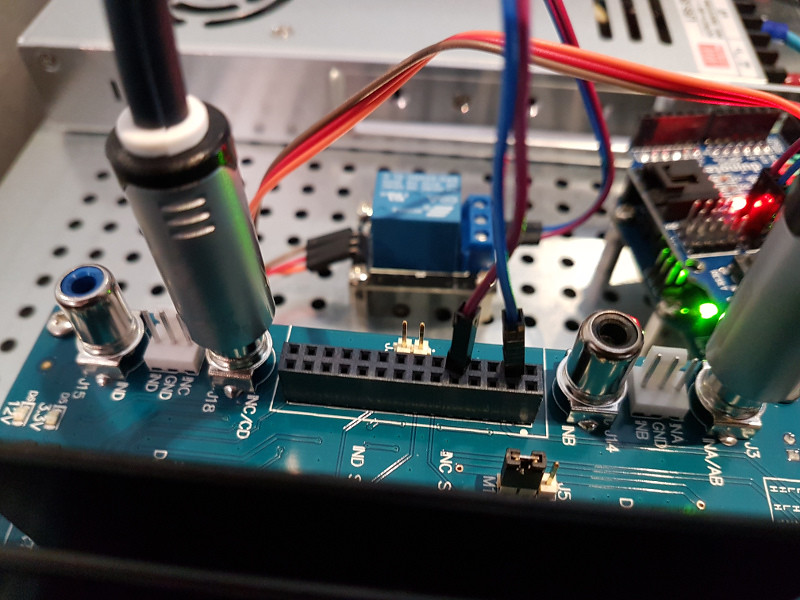
I took a similar approach using an arduino and 5V relay. I programmed the arduino to switch the relay to open/close via a IR receiver and codes. I then programmed my Harmony remote control to switch the relay. I used the red/yellow codes from a Samsung TV (I have a Sony TV).
Reading that this board is more suited to 8 ohm speakers. I cant see anything about this on ti site. My speakera dip to 3.5 ohm or lower. Can someone clear this up?
Nothing to worry about, the 3255 does 4R with no problems. It just runs a bit hotter due to higher supply nominal voltage and a bit higher Rds(on) values for the FETs. The point, the 3251 does 4R better might come from the data sheet, where they specify lower output loads for the 3251 compared to the 3255 where they limit to 6R for voltages higher than 51.5V. This all comes from supply voltage point of view. If you don’t push the amp to limits, they also do less than 3R. That’s it. to sum it up, lower load impedance at higher supply voltage gives more heat which needs to get away. The amp may in into an overvoltage or over current fault if pushed hard.
-> Don’t worry, leave as is.
I want to build an amp but after reading many threads I realized this project involves a lot of work that above and beyond my basic knowledge of electronics. Having said that, will any of you fine gentlemen (experts) willing to build and amp for me or sell me a good amp I would appreciate it.
Specs are TPA3255 in 2.1 setup (not the Chinese generic or YJ boards)
power supply preferably 600whats/ 48 volts input 220-240 v 50hrz
Bluetooth module capable of Aptx HD
suitable case
Preferably finless design
Preferably with volume/ treble / bass control
no pops or noise
Specs are TPA3255 in 2.1 setup (not the Chinese generic or YJ boards)
power supply preferably 600whats/ 48 volts input 220-240 v 50hrz
Bluetooth module capable of Aptx HD
suitable case
Preferably finless design
Preferably with volume/ treble / bass control
no pops or noise
Hi Think -
I removed the heat sink - it is trivial, just two screws and goes back on easily so if you want to try should be pretty straight forward. You may be able to read the resistor values (R36, R52) but the writing is tiny - I measured with meter (9.9k ohms) to confirm what I thought the code was.
Yes, per your diagram, I was going to make a simple molex connection from jumper J17 with two wires to the capacitors (C55 and C63) to ground them - this would give me the option of grounding the pull down resistors vs leaving them in the native state simply but plugging / unplugging the molex connector into J17. These capacitors (C55 and C63) are on the bottom of the board so it is not necessary to remove the heat sink and they are a bit larger than resistors (R36, R52) so easier to make solder connection.
My question regarding the TI link with the TPA3255: Issue When Using PBTL Mode -
it is not clear to me if the issue only when he was testing PBTL mode at or near full power or ?
Cheers!
Sorry hombre for being slow to respond.
It reads like a latch-up condition. I'm surprised you need this guy in PBTL mode (2 ohm subwoofer driver?), but I would follow the TI's recommendation and ground the capacitor if running PBTL (unless you're confident shorting out the small resistors, as the whole point of having PBTL is to be able to run the system hard, where this problem seems most likely to show up. If you have a couple drivers in parallel, it might be worth just running an extra set of wires BTL to the individual drivers.
Last edited:
Thanks DPH!
I don't know if I necessarily 'need' PBTL mode and I do not plan on running hard or really even at moderate levels, but rather I am trying to emulate the configuration of my Genesis loudspeaker servo amps which as you correctly deduced, drives two low impedance woofers in parallel which winds up being about / less than 2 ohms. I am considering as you suggested running the two woofers individually in BTL mode and just using TPA3255EVM as is. Right now, I have it working using BTL, single input, single output and both woofers in parallel but have not turned the volume up. Of course, only using half the available power this configuration.
Any thoughts on what would be the difference / (dis) advantages of PBTL [one input driving two 4 ohm drivers in parallel] vs BTL [two identical inputs driving two separate 4 ohm drivers] ?
Thanks!
Is this board any good?
I anyone familiar with this board?
tpa3255 dc 50v class d hifi digital audio amplifier board 300w + 300w active components module Sale - Banggood.com|Shopping USA
The price is great. What problems does this board have over the EVM board?
Thanks
I anyone familiar with this board?
tpa3255 dc 50v class d hifi digital audio amplifier board 300w + 300w active components module Sale - Banggood.com|Shopping USA
The price is great. What problems does this board have over the EVM board?
Thanks
I anyone familiar with this board?
tpa3255 dc 50v class d hifi digital audio amplifier board 300w + 300w active components module Sale - Banggood.com|Shopping USA
The price is great. What problems does this board have over the EVM board?
Thanks
read it.......i know this board partly
")
https://www.diyaudio.com/forums/class-d/309813-wrong-tpa3255-46.html#post5595549
its a smal version of the tpa3255...you will not get the same power as an EVM board because the implementation is not the same...heatsink...regulator(LM2575T...etc..) some boards are not best quality...but its sound nice after moddding....
chris
Out of box tpa3255 BT AYAMA
Hi, mates. It is my pleasure to make step in Damps . I got board tpa3116 with HP power adaptor 18v/3,5A from AliExpress and that was starting point to DAmps I was very sceptical before. Having these tpa3116 for a while got tpa3255 from same source with 48v/20A power industrial adaptor . I am feeding b&w rock solid speakets. 8homm/150w it sound just fine. The only reason i am confused that tpa3255 sounds not much louder than tpa3116 on same speakers. Tpa 3255 sounds much deeper more bass but not significant difference in loudness. Any ideas why?
Hi, mates. It is my pleasure to make step in Damps . I got board tpa3116 with HP power adaptor 18v/3,5A from AliExpress and that was starting point to DAmps I was very sceptical before. Having these tpa3116 for a while got tpa3255 from same source with 48v/20A power industrial adaptor . I am feeding b&w rock solid speakets. 8homm/150w it sound just fine. The only reason i am confused that tpa3255 sounds not much louder than tpa3116 on same speakers. Tpa 3255 sounds much deeper more bass but not significant difference in loudness. Any ideas why?
Hi, mates. It is my pleasure to make step in Damps . I got board tpa3116 with HP power adaptor 18v/3,5A from AliExpress and that was starting point to DAmps I was very sceptical before. Having these tpa3116 for a while got tpa3255 from same source with 48v/20A power industrial adaptor . I am feeding b&w rock solid speakets. 8homm/150w it sound just fine. The only reason i am confused that tpa3255 sounds not much louder than tpa3116 on same speakers. Tpa 3255 sounds much deeper more bass but not significant difference in loudness. Any ideas why?
Hi
the gain of the chinese YJ tpa3255 boards is about 27dB. As i read about the tpa3116 some boards have a gain of 30dB.
3db louder could be the result what you hear...
chris
Is a big difference (Sound and built quality) betweent the chinese TPA3255 amp board and IRS2092 IRAUDAM7 board also from china?
I have two IRAUDAMP7 and some TPA3116 and also have a TAS5611 but I am not sure for buying one TPA3255.
Same issue on TAS5611, much lower gain comparet to the TPA3116
I have two IRAUDAMP7 and some TPA3116 and also have a TAS5611 but I am not sure for buying one TPA3255.
Same issue on TAS5611, much lower gain comparet to the TPA3116
Make sure your source can output 2 volts rms and your power supply is 48vdc and can maintain that level when playing loud. You should then be able to drive the tpa3255 well into clipping and beyond full power. Remember that your ears are not linear but more logarithmic. An old rule of thumb is for something to sound twice as loud you need 10x the power. Similarly for something to sound 1/2 as loud you need 1tenth power. We can easily hear a few thousanths of a watt.
Thanks, mates. Will try to feed tpa3255 via notebook fue higher output voltage. Feeding via iphone & blutoth or ipad direct earphone output makes no significant loudness increase. I am still wondering how these D amps are playing even on max level without distortion and keep cold, feeling like they have a lot reserves in power.
Here is lot description i got tpa3255 Online Shop AIYIMA TPA3255 Bluetooth 4.2 Audio Amplifier 300W*2 HIFI Class D 2.0 Channel Digital Amplifier Sound System Speaker Home Theater | Aliexpress Mobile. Not sure about gain listed there. Gone plug in notebook.
- Home
- Amplifiers
- Class D
- TPA3255 - all about DIY, Discussion, Design etc