Hello . Tell me, is it worth buying this model of amplifier? Read the subject. Is there a lot of explosive noise when switching on or off ? With respect.
As I mentionned : the TPA3255 version does not have anti pop....the TPA3251 one yes.
So I Would go for the second option
I might as easily ask: "did you try with a balanced source and opamps bypassed?"
And tube fans might as easily ask: "did you try with a tube preamp?"
etc, etc.
There are many pathways to find "your sound". The pathway I'm likely to follow next is APEX class-AB.
But your innovative opamp-swapping has not gone unnoticed nor unappreciated - in fact, in an earlier post I mentioned to forum member saddevil your use of the OPA1622 -
https://www.diyaudio.com/forums/class-d/287470-tpa3255-diy-discussion-design-etc-177.html#post6087586
You are right... Sound is subjective Somewhere.
Tell me more about Apex AB ?
100W Ultimate Fidelity AmplifierTell me more about Apex AB ?
It's a long forum thread with many different APEX amplifier/preamplifier designs discussed, but the main one is the AX14.
Thanks! Although the difference isn't that big and most probably inaudible at these low levels, it would be delightful if TI would have shown how to impement PFFB in their EVM board.Thanks for the offer but unfortunately I already bought mine.
After more digging I found a TI document (attached) on how to implement the PFFB and the graphs (p 43 and up) doesn’t seem to show a drastic difference w the added PFFB si it’s all good. Of course graph doesn’t tell you the sound difference. Very nice of you though.
BR
Eric
Best regards!
Hi
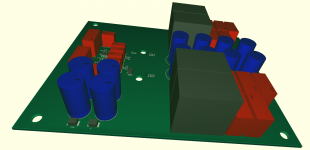
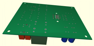
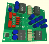
Schematic ist nearly finished !!
Including PFFB and optional additional snubber
Single ended to symetrical converter ist realized with OPA1632.
Attachments
A
This Layout was designed for sagami 7G31A inductors.
Good saturation Limit, but weak Rdc Performance.
Newest Layout is for Low Rdc inductors Like
Würth or Bourns PQ2617BHA-220K
One question :
PFFB Return is connected after Filter to Output of OPV via resistor .
Then follows a coupling capacitor to input of TDA.
At the Moment, OPV ist driven by 12V .
Ist ist better to use 24v or symetrical Power supply?
Output of PFFB ist an Offset voltage of this Output Channel.
PFFB results in a loss of gain.
Opa has to be calculated to compensate the loss of amplification
But what is with impedance or to much voltage or dc fault on output
Last edited:
A
Newest Layout is for Low Rdc inductors Like
Würth or Bourns PQ2617BHA-220K
Attachments
Although this question isn't TPA3255 specific, I'll ask it here anyway ") .
.
The THD+N for the TPA3255 chip with single-ended output is .04%.
The THD+N with BTL output is .006%.
As I understand it, in BTL mode, the even-order harmonics are cancelled out at the driver. Are the even-order harmonics on each of the two BTL tied amps in phase, even though the amplified signals are inverted?
Why aren't odd order harmonics cancelled out? Are they inverted as well?
Is the cancelation of the even-order harmonics the reason for the improvement of the THD+N?
Mike
.The THD+N for the TPA3255 chip with single-ended output is .04%.
The THD+N with BTL output is .006%.
As I understand it, in BTL mode, the even-order harmonics are cancelled out at the driver. Are the even-order harmonics on each of the two BTL tied amps in phase, even though the amplified signals are inverted?
Why aren't odd order harmonics cancelled out? Are they inverted as well?
Is the cancelation of the even-order harmonics the reason for the improvement of the THD+N?
Mike
As I mentionned : the TPA3255 version does not have anti pop....the TPA3251 one yes.
So I Would go for the second option
Thanks for the answer. Are you talking about Aiyima tpa3251? Does it have the same sound quality as tpa3255?
Regards, Oleg.
I think Aiyima is seller, amp is TILEAR XZD-1752.
What is a TILEAR XZD-1752??
Aligatrkil is asking about this amplifier's sound quality compared to the same manufacture's TPA3255 version:
Amazon.com: AIYIMA 2 CH TPA3251 Digital Audio Amplifier 175W +175W HiFi Mini Power Amplifier NE5532 High Power Full Frequency Class D Amp Home Professional (Silver): Home Audio & Theater
Thanks for the answer. Are you talking about Aiyima tpa3251? Does it have the same sound quality as tpa3255?
Regards, Oleg.
Yes TPA3151 these both amplifiers are using almost the same PCB and components. Removable OAP DIP8 as well.
TPA3251, as you know is less powerfull but includes an anti pop.
What is a TILEAR XZD-1752??
Aligatrkil is asking about this amplifier's sound quality compared to the same manufacture's TPA3255 version:
Amazon.com: AIYIMA 2 CH TPA3251 Digital Audio Amplifier 175W +175W HiFi Mini Power Amplifier NE5532 High Power Full Frequency Class D Amp Home Professional (Silver): Home Audio & Theater
They are exactly the same thing:
TPA3251 Digital Audio Amplifier HIFI Power Amplifier 2.0 175W *2 streo Home Professional Amp NE5532 Super TDA7498E/TPA3116-in Amplifier from Consumer Electronics on AliExpress
Neither Tilear or Aiyima are manufacturers, they are marketers of other peoples products.
Beware of that brittle DC connector! I'd bet that it ain't capable of the input power that is needed for 2 x 175 W output.
Best regards!
I have the TPA3255 one... I am using a Linear 300W / 40V PSU without issues.
And you feed it through this small notebook type coaxial power connector without any issues, especially without it getting hot during longer periods of high output power?
Best regards!
This is a typical DC 2.5mm plug.
Nothing bad to report.
Yes TPA3151 these both amplifiers are using almost the same PCB and components. Removable OAP DIP8 as well.
TPA3251, as you know is less powerfull but includes an anti pop.
Thanks for the answer. The 3255 amplifier is sufficient for a room area of 16 square meters.
Hi,
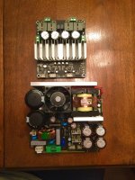
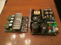
Just received today my TPA3255 power amp module and a few days ago my 600W 47Vdc supply from Cresnet. These 2 items will fit nicely in a enclosure from eBay, do a search w 1907 enclosure. Once I have received my enclosure I’ll post some pics. The 3e Amp is surprisingly small...For now, this is what I have;
Just received today my TPA3255 power amp module and a few days ago my 600W 47Vdc supply from Cresnet. These 2 items will fit nicely in a enclosure from eBay, do a search w 1907 enclosure. Once I have received my enclosure I’ll post some pics. The 3e Amp is surprisingly small...For now, this is what I have;
Attachments
- Home
- Amplifiers
- Class D
- TPA3255 - all about DIY, Discussion, Design etc