Single supply. (Up to 51V for the TPA3255)
Wow that's amazing, that feature brings more chance to make it popular because it would be easier to power it, many of us already have some single power supplies at home, however the average voltage value floats around 19V laptop power supplies
 ... which after all buying a dedicated power supply may be required. Anyway its cheaper and easier to find a single power supply in the online market than a dual voltage. But hey! what about those cheap dc-dc step up voltage converter boards? do you know if they are suitable to power up amplifiers like this? because I have some atx psu's ready to be used in pair with one of these cheap dc step up converters I have seen on amazon, which can handle very high currents.
For light loads (or mobile applications), this might be an option if you get one of the 20A switchers. Output power is limited by primary switching current. So for 12V 20A you're limited to 240W cont. power. Transient power is higher, of course but THD might/will rise if you pushing it hard. YMMV.
I wouldn't recommend if it can be avoided.
I wouldn't recommend if it can be avoided.
Finally ordered the pcbs.

great work
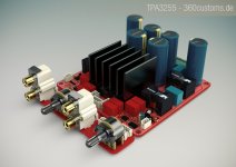
i notice 5 sets of pin input/outputs connectors im guessing one is a signal input and a fan and a pre amp what are the other connectorThere is:
Molex SPOX series
3-pin in the middle: Left, GND, Right for BTL/PBTL
3-pin left/right middle: + GND - for differential in or SE Mode
2-pin right: +12V 0.15A Aux Voltage
2-pin left: external Reset/Mute Input
JST-XH series should also fit for receipts and plugs - i prefer the SPOX.
Not shown is the 3-pin Molex connector for a Standard 12V 0.15A Fan. Thermal control is either 2-stage via Clipping signal or NTC based sensed isolated under the heatsink.
Regards.
Whoaaa looks good!
I:
-do NOT need a volume control.
-need RCAs soldered.
-need speaker binding posts soldered.
-do NOT need an amp case.
I would like to know what would I have to solder/connect,etc. to make this board ready to play?
And of course how much this will cost to buy?
I:
-do NOT need a volume control.
-need RCAs soldered.
-need speaker binding posts soldered.
-do NOT need an amp case.
I would like to know what would I have to solder/connect,etc. to make this board ready to play?
And of course how much this will cost to buy?
So, what will I have to do to make your board/amp work if I buy it? Thanks.There's no place for binding posts, all is connected via Phoenix 5.08 terminals.
the boards come bare i have had experiences of building doctor mords amps and im very impressed
you will have to solder the parts on yourself i can also tell you that doctormord likes to use very small surface mount components so you might want to brush up on you solder/reflow skills before you contemplate it and a cheap usb microscope was was a must for me as my eyes are not getting any younger
you will have to solder the parts on yourself i can also tell you that doctormord likes to use very small surface mount components so you might want to brush up on you solder/reflow skills before you contemplate it and a cheap usb microscope was was a must for me as my eyes are not getting any younger
Does this circuit use simple power supply? I mean, not dual voltage, just like tpa3116. Its a kick in the *** watching nice amplifier boards on ebay and discover that they require special dual voltage power sources.
If you dare building your own amplifier, I hope you know that there is nothing special to a dual voltage power source.
If you can't make your own, their is plenty of ready made PSU's with dual supply.
the boards come bare i have had experiences of building doctor mords amps and im very impressed
you will have to solder the parts on yourself i can also tell you that doctormord likes to use very small surface mount components so you might want to brush up on you solder/reflow skills before you contemplate it and a cheap usb microscope was was a must for me as my eyes are not getting any younger
OK then, out of my league unfortunately
I've taken care on that, so 95% is 0603 and up. Cloud had the small red blocks if i remember correctly.
If i had the time, i'd build up boards ready to use.
(Unfortunately i'm still studying and have to work a lot to pay my bills.)
I'll finally think about a group buy with the boards made by a local assembly company once the implementation is proven to work as expected. Bare boards with bom and assembly instructions are available earlier.
Btw. Power supply needed is single voltage, 48V 10- 20A to go for the full distance. Haven't tested yet, normally use the amps with dcdc boost supply on my bike.
Last edited:
I've taken care on that, so 95% is 0603 and up. Cloud had the small red blocks if i remember correctly.
If i had the time, i'd build up boards ready to use.
(Unfortunately i'm still studying and have to work a lot to pay my bills.)
I'll finally think about a group buy with the boards made by a local assembly company once the implementation is proven to work as expected. Bare boards with bom and assembly instructions are available earlier.
Btw. Power supply needed is single voltage, 48V 10- 20A to go for the full distance. Haven't tested yet, normally use the amps with dcdc boost supply on my bike.
Can I ask this then, do you send EVERY necessary part to make it ready to play or do I need to buy anything on my end? I can find someone to solder the parts. Would it also be possible to connect (I know the no space issue) binding posts to Phoenix 5.08 so I can connect my cables with banana plugs?
In the past i supplied a Mouser BOM/Basket to order yourself, just because if i will send everything in a box, i need to declare it for the (US) customs n stuff. It's better to order on yourself, as Mouser is a US based supplier. (Reimport is always a "bad" thing.)
This also is more ecofriendly.
You don't need to stuff the phoenix connectors. You can either solder screw-terminals or wires directly.
This also is more ecofriendly.
You don't need to stuff the phoenix connectors. You can either solder screw-terminals or wires directly.
At the moment I am playing with a TPA3255 EVM Module. All in all it is a nice design and looks like really fine engineering to me - I would call it the bleeding edge of current class-D-technique.
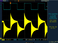
As always, there remains some room for improvement. Personnelly I have always been skeptical about pre-filter feedback because in that case the LC output-filter may ring excessively on its resonant frequency. This does not show up in lab test environment using low-inductive dummy loads, so you won't find this in data sheets. But in reality no loudspeaker does provide a resistive impedance of 4 or 8 ohms at 50kHz but is more or less pure inductive at ultrasound frequencies. Without further provisions like an adequate snubber, every sharp transient will excite this resonant circuit with or without speaker load resulting in more or less severe overshoot and ringing. To stimulate this effect I drove the TPA3255EVM with a 330Hz square wave of less than 2us rise-time width no output load at all.
As expected there is significant ringing (1.plot).
It should be mentioned that this ringing requires a very fast transient at the input to be excited, "normal" audio-signal will not show this effect so things are not as critical as this plot might suggest.
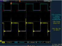
Anyway, I fiddled around with some compensation network and discovered that one 47pF-capacitor placed between output D and inverting input U6.pin2 yields a significant improvement of square response depicted in the 2. plot.
Further increasing this capacitor to 100pF established self-oscillation thus 47pF seems to be close to optimum.
As always, there remains some room for improvement. Personnelly I have always been skeptical about pre-filter feedback because in that case the LC output-filter may ring excessively on its resonant frequency. This does not show up in lab test environment using low-inductive dummy loads, so you won't find this in data sheets. But in reality no loudspeaker does provide a resistive impedance of 4 or 8 ohms at 50kHz but is more or less pure inductive at ultrasound frequencies. Without further provisions like an adequate snubber, every sharp transient will excite this resonant circuit with or without speaker load resulting in more or less severe overshoot and ringing. To stimulate this effect I drove the TPA3255EVM with a 330Hz square wave of less than 2us rise-time width no output load at all.
As expected there is significant ringing (1.plot).
It should be mentioned that this ringing requires a very fast transient at the input to be excited, "normal" audio-signal will not show this effect so things are not as critical as this plot might suggest.
Anyway, I fiddled around with some compensation network and discovered that one 47pF-capacitor placed between output D and inverting input U6.pin2 yields a significant improvement of square response depicted in the 2. plot.
Further increasing this capacitor to 100pF established self-oscillation thus 47pF seems to be close to optimum.
Attachments
Who drives an amp with <2us square wave and no load in practice?
Certainly that may be discussed - on the other hand: Who loads his amp with a pure resistive load at 50kHz?
- Home
- Amplifiers
- Class D
- TPA3255 - all about DIY, Discussion, Design etc