... To make the list complete though, I am going to list all of the problem of the board including those already mentioned. ...
So, this is the intro. page .. as days progress, I'll get to work making all of this information more visual and understandable.
Thank you mgshightech.
It is still a wall of text and i cannot make a personal list of priorities for myself to mod this board.
Maybe it is absolutely pointless without a osci.
look at the parts list and the images. Every important mod is on the list and the images.
priority #1 get a heat sink on the irs2092 chip and make sure the transistors are heat sink greased and solidly mounted before you even dare power this up or all the fun will not last ... also .. I would not try doing this without 7 amp fuses on each incoming power line. If something goes wrong, those fuses will likely save you.
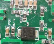
priority#2 mod the feedback loop (the 200k resistor .. there's only one on the board) as shown on the image
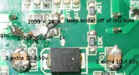
it's close quarters, so testing with your meter will help you to know what's dangerous. That resistor labelled 512 has one end that can be allowed to accidentally attach to the end of the 200k resistor (not the 150 pf cap) because it's already connected in the circuit layout. The tiny hole right next to that connection however is absolutely off limits. One tiny thread of solder to that hole and you'll have trouble .. I think you'll burn the fuse cause it will instigate exclusive positive feedback. One of the transistors will turn on solid. All of this detail is visible on the image that shows the feedback loop mod.
When you get the board, the 200k resistor connects the transistor outputs straight to the rest of the feedback circuitry. De-solder it and very carefully put it on an angle so you can connect the 1k resistor to the connection closest the main transistors that you just took the 200k resistor off of. The 200k resistor remains connected at the end closest to the rest of the feedback circuitry. Angle the two resistors so that they meet each other and solder them together at that meeting .. then connect the 150 pf cap to that junction and point it towards the little ground pole. It won't reach the ground pole, so you have to add some solder or a little wire and some solder to get it there .. Check carefully for stray connections and errors this is the hardest part of the mods cause those tiny parts wiggle all over..
priority#3 swap the output filter cap for 0.27 uf as on the parts list and add the dampener circuits as shown on the images. One of the dampeners is 0.1 uf with around 3 ohms in series from top pole to bottom pole .. the important one is 0.22 uf with 4.7 ohm, 5 or 10 watt in series from speaker output to ground .. also 0.33uf with 4 ohm 10 watts is what I moved to .. both options work. Least important dampeners .. 2 small .01uf caps, each from one of the power poles to ground.
at this point I believe you'll have a functional board, but #5 may also be required for this.
priority #4 add heat sinks also .. one to the output inductor and one to the main heat sink
priority #5 add additional 10 uf 50v ceramic caps to the floating power supply so that it stores plenty of charge.
use heat sink plaster to attach heat sink to irs2092 chip
use heat sink grease to attach heat sink to inductor until you're satisfied everything is aok .. then remove heat sink grease and plaster it on. I would not use heat sink plaster to attach an additional large main heat sink .. in stead I would use screws or .. in my case, I'm going to use heat sink grease and a string and some springs for the final setup .. for the test setup, I just set the heat sink on top, with heat sink grease. For a fabulous set of heat sinks, go to ebay and look up "antminer s1"
priority #1 get a heat sink on the irs2092 chip and make sure the transistors are heat sink greased and solidly mounted before you even dare power this up or all the fun will not last ... also .. I would not try doing this without 7 amp fuses on each incoming power line. If something goes wrong, those fuses will likely save you.
priority#2 mod the feedback loop (the 200k resistor .. there's only one on the board) as shown on the image
it's close quarters, so testing with your meter will help you to know what's dangerous. That resistor labelled 512 has one end that can be allowed to accidentally attach to the end of the 200k resistor (not the 150 pf cap) because it's already connected in the circuit layout. The tiny hole right next to that connection however is absolutely off limits. One tiny thread of solder to that hole and you'll have trouble .. I think you'll burn the fuse cause it will instigate exclusive positive feedback. One of the transistors will turn on solid. All of this detail is visible on the image that shows the feedback loop mod.
When you get the board, the 200k resistor connects the transistor outputs straight to the rest of the feedback circuitry. De-solder it and very carefully put it on an angle so you can connect the 1k resistor to the connection closest the main transistors that you just took the 200k resistor off of. The 200k resistor remains connected at the end closest to the rest of the feedback circuitry. Angle the two resistors so that they meet each other and solder them together at that meeting .. then connect the 150 pf cap to that junction and point it towards the little ground pole. It won't reach the ground pole, so you have to add some solder or a little wire and some solder to get it there .. Check carefully for stray connections and errors this is the hardest part of the mods cause those tiny parts wiggle all over..
priority#3 swap the output filter cap for 0.27 uf as on the parts list and add the dampener circuits as shown on the images. One of the dampeners is 0.1 uf with around 3 ohms in series from top pole to bottom pole .. the important one is 0.22 uf with 4.7 ohm, 5 or 10 watt in series from speaker output to ground .. also 0.33uf with 4 ohm 10 watts is what I moved to .. both options work. Least important dampeners .. 2 small .01uf caps, each from one of the power poles to ground.
at this point I believe you'll have a functional board, but #5 may also be required for this.
priority #4 add heat sinks also .. one to the output inductor and one to the main heat sink
priority #5 add additional 10 uf 50v ceramic caps to the floating power supply so that it stores plenty of charge.
use heat sink plaster to attach heat sink to irs2092 chip
use heat sink grease to attach heat sink to inductor until you're satisfied everything is aok .. then remove heat sink grease and plaster it on. I would not use heat sink plaster to attach an additional large main heat sink .. in stead I would use screws or .. in my case, I'm going to use heat sink grease and a string and some springs for the final setup .. for the test setup, I just set the heat sink on top, with heat sink grease. For a fabulous set of heat sinks, go to ebay and look up "antminer s1"
Last edited:
the output filter cap needs replacing .. original one is 1uf 100v .. change to 0.27 uf 275v as listed on the parts list The new cap has to be angled to fit, and the ground leg won't fit in its hole, so scrape the ground plane with a razor and solder straight to the ground plane
Attachments
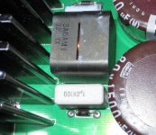
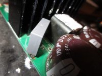
the dampener circuits shouldn't need pre-post images .. the images are already shown .. they are the glued-on looking capacitors and resistors some to the underside of the board some to the speaker output. These dampeners kill the parasite. Also, the post image for the feedback loop mod shows additional 10uf 50v ceramic caps soldered to the pre-existing floating power supply caps.
there is some data on the ljm l30D here on this site: http://www.diyaudio.com/forums/class-d/280531-l30d-irs2092-irfb-4227-iraudamp9-mydiy.html looks like it's running hot, and it does not have the overtemp protection component that the iraud200 has ... don't mean to be rude, but at this point, I would choose the iraud200 Plus mods ... over the L30D (iraudamp9 knockoff) .. This modded board is running flawlessly .. it runs cool at quiescence.
the output filter cap needs replacing .. original one is 1uf 100v .. change to 0.27 uf 275v as listed on the parts list The new cap has to be angled to fit, and the ground leg won't fit in its hole, so scrape the ground plane with a razor and solder straight to the ground plane
Sorry I cannot extract any info regarding the board that you are working with. Is it the L30D board that LJM sells? Or it is one of the EBAY ones? Did you actually tried the LJM L30D? I neither have the time and knowledge to do what you have done. Just would like to get something that will work right out of the box. Thanks!
Regards,
ljm_ljm keeps claiming the L30D works great ... this is not the L30D, but the iraud200 that you can find in a lot of places. Try ebay for example. Others have not been satisfied with the L30D .. Looking it over ... the L30D is missing the overtemp protection and has a smaller heat sink ... I don't think it's as good of a board, I don't know for sure whether it will or won't work out of the box for you. I have not tried the L30D .. might be willing to mod an iraud200 for someone else at a price .. I don't know what to expect from an L30D. I would love to see some more comments on the L30D thread here on DIY audio, but not enough info. there to be convinced of anything. Someone else claimed it didn't work for him. ljm_ljm claims that the L30D works great at +/-75 volts, but has problems at significantly lower voltages. ljm_ljm I believe designed and markets the board, so people really need more opinions than his. I didn't design and haven't marketed the iraud200, so the information here and in the other iraud200 thread has no monetary motivation.
Last edited:
The L30D and the iraud200 have the same basic goal .. to empower a pair of irfb3227s .. the iraud does it by adding a heat sink to the 2092 .. which the boards on the market seem to be forgetting to get on there .. the L30D uses a gate driver in stead. I have looked far and wide and been unable to find a respectable name brand board like sure electronics or such that offers the same or similar feature set. i.e. +/- 70v approx. 2 ohm load and around 800 watts rms. This is an extremely desirable amplification goal. Right now, I am happy with the iraud200 as modded per these instructions .. but I have used it as a sub driver. For a full range driver, I think the feedback loop may need to be adjusted some more because it allows some ambient e-m fields to make noise. I'm pretty sure I know what to do about that though. I have met that problem in earlier work.
ljm_ljm keeps claiming the L30D works great ... this is not the L30D, but the iraud200 that you can find in a lot of places. Try ebay for example. Others have not been satisfied with the L30D .. Looking it over ... the L30D is missing the overtemp protection and has a smaller heat sink ... I don't think it's as good of a board, I don't know for sure whether it will or won't work out of the box for you. I have not tried the L30D .. might be willing to mod an iraud200 for someone else at a price .. I don't know what to expect from an L30D. I would love to see some more comments on the L30D thread here on DIY audio, but not enough info. there to be convinced of anything. Someone else claimed it didn't work for him. ljm_ljm claims that the L30D works great at +/-75 volts, but has problems at significantly lower voltages. ljm_ljm I believe designed and markets the board, so people really need more opinions than his. I didn't design and haven't marketed the iraud200, so the information here and in the other iraud200 thread has no monetary motivation.
Thank you for the reply. Much appreciated.
Yup. LJM mentioned that the operating temperature of his board was quite high but seemed to stablise at ~ 50oC (not 100% sure). He did mention that temperature protection is not implemented since the data sheet described a 104oC operating temperature and no caution was given (which implies anything less than that should be fine(?) I wonder may be installing forced air cooling is a good idea, as LJM pointed out high temperature is not good to component longevity.
I believe raudamp9 clones boards appears on EBAY quite recent (I might be wrong but I have been searching amps in this category for a while) , so there are not too many reports/feedback.
I am not too worry about LJM's reputation since he has been around here for a while and quite a number of people use his boards and are happy about it. For those who are skill in the art might find his board are not state of the art, but I think his stuffs should work under typical conditions Anyway, as always, buyers beware.
Thank you again for the comments.
Regards,
No experience with L30 , but with L15D's from LJM for years now , running this Amps on +/- 55Volts . No glitch what so ever ! Very reliable in Australian conditions , sometimes 40+ ambient or more and had them playing LOUD for hours at several party's ! For me these little amps are "state of the art" after some minor component upgrades .
If your language skills permit , have a look at "http://www.diy-hifi-forum.eu/forum/archive/index.php/t-5010.html"
They compared the LXXD's with many other class D amps and LJM is still favorite in Germany !
Heat is no problem , even with the tiny heat-sinks !
LJM advises to use forced cooling with L30 in certain conditions , OK ( Google ?) translation is probably a bit off , but use your imagination
")
Cheers ,
Rens
Last edited:
I tried his L25D and it may have been fine for an 8 ohm load, but for 4 ohm, it simply overcurrented. It was next to useless. For various reasons I could do little to fix it. Chopping the gate resistors down helped though. The board its self only claims 8 ohms ... the ad claimed 4 ohms. .. so it may be that LJM gets the plus points but the individual marketing it needs a kick.
I mounted my iraud200 boards to a very large heat sink .. then I added another very large heat sink to the transformer that powers them. Not necessarily cause they became excessively hot (after modding) but because of the longevity issue mentioned above. My pioneer sx-1250 is now 40 years old. I recapped it and am hoping for another 40. I would like to see this class D setup hang in there for its own 40 years. I hate worrying about and replacing stuff that breaks all the time. I could have left these boards as they were after the feedback loop mod with their parasites heating up the output components ... they both worked. But I knew that the transistors, inductors and output filter caps were taking a beating, and that you can't expect that to last forever. Stuff happens, like the extra heat invites slow oxidation of the transistor legs to crawl up into the transistors... or migration of the atoms in the P-N junctions over time. Chemical reaction rates tend to approx. double every 10 degrees Celsius .. so you could potentially double the life time of your item by knocking 10 to 15 degrees celsius off of it. .. Come to think of it ... the iraud200 uses only 4 electrolytic caps, which are known to sometimes dry out over time. .. the rest are ceramic .. longer life.
.. LJM's L25D has output filter dampeners in it, so LJM is not unaware of the need to squish parasites. His L25D also correctly uses the feedback loop delay cap. He seems to be on track. If his boards are running hot, I suspect its more likely caused by some delay in the gate drive strategy that leaves the transistors partially on for a significant amount of time, or perhaps excessive bus pumping or cross conduction. .. One would know more about it by testing the temp. of the inductor.... A parasite will beat up the inductor as well .. otherwise, what I was just saying will only heat the main transistors. LJM is likely to get another board out at some point almost identical to the L30D, but capable of 1 ohm loads by adding in a second pair of transistors. The iraud200 strategy can not do that. .. Once again, LJM is on the right track. Just right now, I would not prefer his L30D over a corrected iraud200 .. You can get the iraud200 to superior condition to the L30D for about $3 - $4 in parts. Except for the sink on the 2092, The extra heat sinks are not a requirement. I like the overtemp protection and the larger heat sink.
However .. to add to that, I think I would say that the L30D probably has a more noise free feedback loop, so it will have less noise which will matter for the higher frequency ranges. I don't feel like messing with my feedback loops right away, so details on how to fix the e-m receptivity of the iraud200 won't show up until I do it, or someone else does it. But for starters, it will probably begin with replacing the 200kohm feedback resistor with something lower like 150kohm or 120 kohm. The high 200k of impedence helps to open up the inputs of the 2092 chip to ambient e-m fields .. I knew that was a stupid as soon as I saw it, but if you change that resistor, you will probably have to/need to change a couple more with it... My whole attitude was to let top notch vintage amp circuits drive the high frequency stuff and use Class D to drive inefficient, bottomy, high x-max sub woofers that seem like they can never get enough power. You can switch to low x-max, high efficiency drivers at the cost of your 20-35 hz range. I insisted on getting the full audio spectrum.
Last edited:
LJM advises to use forced cooling with L30 in certain conditions , OK ( Google ?) translation is probably a bit off , but use your imagination
Rens,
Thank you for the pointer. I will look up the link. I am thinking about forced air cooling too.
Regards,
It's the JLA-1200D coming from the philippines that is a full amp9 implementation .. you can find it on ebay .. 4 irfb3227's however, they only rate it for 2 ohms ... 1200 watts. you'll have to have a very sturdy +/-75v supply for that .. normally, a transformer droops a lot with high current .. too much to achieve the 1200w into 2 ohms ... I think that to do this you would have to have a switching supply that refused to droop more than a couple volts. .. I'm surprised they haven't rated that board for 1 ohm. Enough transistors for it, but I'm guessing the traces, inductor etc. aren't ready for it. .. This board is about double the cost of the iraud200. .. so, basically, they get two more transistors on there and double the price tag. I don't know that it even comes with its own heat sink .. I saw images before of the board with a cheesy little heat sink .. now I see none .. You'll likely have to add some heat sink to this one.
machines gun noise
Hi mgshightech,
I have the same board. After rectifying, i have +- 60v.
But the board doesn't start. It switches on and imidiately off.
Does undervoltage protection kick in?
Would it be a solution to replace the 3,6k resistors with half the value, or some smaler value?
Thanks for you thoughts
Best regards
Olaf
I saw it switching on and off again, but it was not immediate. In my case, the problem was overtemperature. It took about 5 minutes or so to heat up the sink and trip the overtemp element on the left side.
I assume you heat-sink-greased everything.
That stopped happening when I adjusted the feedback loop as shown, but it still heated up to almost tripping until I killed the parasite. I'm trying to think of what might cause it to turn off immediately but not actually kill the transistors. If the parasite problem was really bad, it might move enough current to trip the overcurrent function. If that is what is happening, then it would just wait a few seconds most likely and switch back on, only to switch back off again. I donno, never tripped overcurrent on it, not even with 2 ohm load.
What makes it turn back on? Is it powering it up?
+/- 60v should not be undervoltage range for the board, though I never tried it. The board probably drops to 65 or less if I am driving a lot of power. hmmm ... however, if your +/- 60 volts does not want to deliver much current, the board will draw around 100 watts if the parasite is active. It might draw the 60 down to 55 or lower. One possibility is that your +/- 60 volts isn't holding up under load.
I would ohm out the thermal protection element on the left both before and after tripping. I believe they are high resistance (open) when the board is functioning properly. That element is the one heat sinked with just two legs.
Thanks for your reply.
I guess the 60v +- isn`t enough. As soon as I give power to the board, it switches itself on and off, on and off...
I touched the main heat sink and it was cold, so it shouldn`t be overtemperatue.
I already ordered some parts that you mentioned (the 150pF, 1kohm, heatsink for the 2902, thermal paste and the zobel circuit at the output terminals)
But before I apply your suggestions, I wanted to test the board stock.
But no go with 60v in my case (although the seller said supply voltage from 40v to 75v is possible).
Guess I replace the 3.6 k, that supplies the 2092, with smaller values. Maybe 2k.
I want to drive my electrostats from 300- 20kHz.
Right now, my ld15 do this well, but if it goes louder, they switch off.
Last edited:
- Status
- This old topic is closed. If you want to reopen this topic, contact a moderator using the "Report Post" button.
- Home
- Amplifiers
- Class D
- iraud200 short story