I am starting this thread because the iraud200 thread started to become too long to read and process because of all of the little experiments, discussions, etc. This thread is only for quick reference on how to manage the iraud200 board. Use the other thread for more info. on fine details and more detailed understanding.
I chose the iraud200 boards from an ebay seller because I wanted a 2 ohm capable single channel board capable of handling around +/- 70 volt power supply and 600+ watts per channel. iraud200 seemed to be the only option available for these specs. The next closest runner-ups were the iraud350 which at best handles a 4 ohm load. The iraud200 and the iraud350 are close cousins. That means that they share some attributes and problems.
Both boards have the fundamental problem that they are way over-driving the irs2092 chip. One of my copies of the iraud350 worked, but eventually it was the irs2092 chip that failed. That board had a small, tall heat sink pasted to the irs2092 chip to help with the problem. I over-currented the transistors and lost them and replaced them with irfb4227 for more current, which the chip was apparently unable to drive despite heat sink because the 2092 was the next thing to go. I thought it might work to try a board that carried the irfb4227 stock, so I went for the iraud200 and hoped for success with 2 ohm loads. I was sorely disappointed up front. I really wanted this to work, so I became determined and eventually I successfully forced the board to behave. I would like to share the secrets of this success with other DIYers who see the iraud200 as a potential option to get what they want.
The iraud200 sports excellent protections and current/power capability. The irfb4227 transistors are magnificent and capable of stunning currents such that just two of them can be used to drive over 20 amps through a 2 ohm load.
When my board(s) arrived, I was greeted with obvious Quality assurance failures that made me very suspicious. No heat sink grease on the transistors .. no heat sink on the irs2092 chip. I did not dare power them up until I had the transistors greased and a tall little heat sink on the irs2092 chip. When the parts arrived for that, I was in for yet more disappointment. The boards fired up and worked beautifully for about 3 minutes. Then they quit. I thought they were burned, but actually not .. the boards sport overtemp protection which had turned the boards off because the heat sink had become too hot (imagine what would have happened with no heat sink grease).
Later, It turned out that the cause of the overtemp failure was a high frequency parasite that resonated in the output filter and leaked back into the feedback loop. Before I knew that though, I learned a lot of things about the board in my attempts to beat this problem. To make the list complete though, I am going to list all of the problem of the board including those already mentioned.
1. No heat sink grease on the transistors (easy fix with heat sink grease)
2. No heat sink on the irs2092 chip which can't drive irfb4227 safely without it. Get a small heat sink from ebay or such about 10mm by 10 mm by 35mm and get heat sink glue to glue it on there .. try not to get the glue on the pins of the chip (don't know how crucial this is .. never became a problem for me)
3. The fudgers did not follow the proper feedback loop specs from the example docs. Don't know why, but they made several changes. First, they eliminated the 150 pf delay cap and accompanying 1k resistor (really bad idea) out of the feedback loop. Second, they slightly adjusted the ohmage of the floating ground (no biggie) third, they eliminated the input capacitor and allowed you to direct DC drive this board .. it should in fact be able to output DC current (interesting, may find uses for this later) . You can forget about the DC input/output option they built in pretty much and not worry about the tweaked floating ground except that I think it adds a little hum to the output. The killer is the elimination of the delay cap and resistor in the feedback loop. This exacerbates the problems we already have, trying to drive the high gate charge of the irfb4227 by boosting the feedback switching frequency to around 800khz. It also feeds the parasite OUCH!!!! This thing is trying its hardest to burn out the irs2092. Turns out that the iraud350 does the same thing. If you have either board, you will want to fix the feedback loop.
To fix the feedback loop, order 150pf ceramic caps rated at at least 150 volts and 1k surface mount resistors of the proper size. This board has a single 200kohm resistor that acts as the feedback voltage reducer. You can continue to use it, only you have to put a 1k resistor between it and the transistors output, then connect the junction between those two resistors to ground through the 150 pf capacitor. This slows down the switching frequency and in my case allowed the board to run without overtemping. However, it was still very hot and it made me nervous to run it/them.
4. Interestingly the high temperature would sometimes disappear for as much as several days, which I eventually learned to be a result of a faulty connection between the output filter capacitor (the big one just behind the heat sink) and ground.. or .. eventually ... a destroyed output filter capacitor. When the connection from cap to ground would disappear, the parasitic resonance between cap and output inductor would die with it, the board would cool off, but obviously, there would be a lot of rf on the output line because only half of the filter would be operating.
5. The output filter capacitor was not rated properly. It should have been 0.47 uf and 200 volts or higher AC rated film capacitor. In stead, it was 1 uf and 100 volt, which the parasitic resonance destroyed after a period of time, leaving a board that didn't overheat, but also basically had no proper output filter capacitor. You will need a high power soldering iron .. like 40 to 60 watt to swap that capacitor out .. otherwise the solder won't melt well enough. .. but don't reach straight for the correct 0.47uf 200 plus volt capacitor to replace this with because it's a potential parasite feeder .. see number 6.
6. After putting the correct capacitor in place, the board(s) still ran dangerously hot. I added some resonance dampening caps and a resistor (I'll show these crucial details in detail) .. this got one of the boards to behave, but the second one didn't because its parasite was a little livelier. I tried tweaking multiple resistors in the feedback loop to change this to no avail. That's how I became convinced that the parasite was living in the output filter. Smaller output filter capacitance in the output filter helped cool the board, so I ordered several options of parts to take that output filter cap position. Eventually, the combination that killed the tougher parasite on the second board was a 0.27 uf film cap rated at 275 volts as the output filter cap, and a second capacitor of 0.22 uf (275 vac film) connected in series with 4.1 ohm 4 watt (suggest at least 5 watts for this 5 ohm is probably fine) dampener resistor across the boards two output terminals. (output and 0 volt .. right next to each other) Whala ... success!!!!!!!!!!!! The parasite could not make it past the tipping point, so it remained a virtual nothing of empty space-time.
7 The board has 3 10uf (nonpolar) ceramic caps that help the floating power supply function. These were smaller than the caps on other variants of the circuit I had seen, so I purchased a bunch of 10uf 50 volt and soldered them on in parallel with the pre-existing caps. This is the first parts change I did to try and fix the boards, which didn't work, so I don't know if it's required or not, but it's a good idea I think.
8 There are two versions of this board .. the 4 ohm version and the 2 ohm version. The 4 ohm version has a smaller output inductor. Yes, I know, there are four pins on the inductors which makes them look like pairs of inductors, but two of those pins are not electrically connected and only stabilize the inductor. If you want the 2 ohm version, make sure it says 2 ohms and maybe double check that the inductor is filling up its (square) space all the way ..
9 also, don't get a version of this board with oversized storage capacitors because they'll get in the way of a heat sink for the output inductor. The output inductors are a little small, so to stay safe, heat sink grease a heat sink to them and then when you are done fiddling, replace the heat sink grease with heat sink glue. The output inductors definitely have to have the heat sink to protect them if the boards parasite problem has not been fixed yet. The main heat sinks are likely to require supplementation as well, especially if you haven't killed the parasite yet.
10 Using ferrite beads on the 0 volt lines to the power supply, I was able to get two of these boards to co-exist on a system with two plus poles and two minus poles that shared a common 0 volt line. This normally risks the 2092 chips getting all befuddled with rf on the 0 volt line that comes from the other board, but I was able to smile by simply putting two ferrite beads on each 0 volt line. Yay!!!!!!!!
So, this is the intro. page .. as days progress, I'll get to work making all of this information more visual and understandable.
Last edited:
OK ... parts list:
from mouser.com :
10uf 50v cap to supplement the floating power supply .. get six or so per board and solder on several extra they are nonpolar, so direction doesn't matter.
81-GRM31CR61H106KA2L
150 pf 200v delay capacitor for the feedback loop .. also nonpolar 1 per board
581-12062A151J
1k resistor to put in front of the delay capacitor 1 per board:
71-CRCW1206-1.0K-E3
0.27 uf 275 volt cap to replace the original output filter cap 1 per board:
80-R46KN32700001K
0.22 uf 275 vac cap to act as the first part of the dampener circuit 1 per board:
80-R46KI322000M2K
4.7 ohm 5 watt to act as the other part of the dampener circuit note: do not use wire wound for this resistor as the inductance may cause trouble 1 per board..
660-MOSX5C4R7J
0.1 uf 250volt cap for second dampener circuit 1 per board:
667-ECQ-U2A104KL
3.3 ohm 2 watt for second part of second dampener circuit 1 per board:
660-MOSX2CT52R3R3J
.01 uf power supply stabilizer cap (2 per board):
594-S103M47Z5UN63J7R
from ebay:
irs2092 heat sink ... just search for the words: heat sink 10mm x 10mm x35 mm
big heat sink/fan system to keep multiple main heat sinks cool .. only necessary for 2 ohm operation, and smaller options may work fine: look up the words: antminer s1
or for a single sink to mount to both boards try searching for these words:
heat sink 182 x 100 x 45mm
heat sinks for the inductors: look up the words:
heat sink 55mm x 50mm x20 mm or:
heat sink 40mm x 40mm x 20mm or:
heat sink 75 x 50 x21 mm (slightly wider than the board and cheaper than the others)
ferrite beads: also on the order linst
sorry I forgot these and can't update the last post
ferrite beads:
look up "ferrite bead" on ebay and select some beads that will fit your wire size .. clam shell type .. get at least 2 per board .. perhaps as many as 4 or 5. Use 2 for the ground line that goes back to the power supply, 2 more on the output line may be good .. one on the input line may also be good .. My ferrite beads were for 3.5mm wire and worked beautifully the iraud200 has its own rf input filter to help protect the input from radio frequencies
the ferrite beads may be unnecessary if you are only powering one board per unique 0 volt reference.
first set of mods
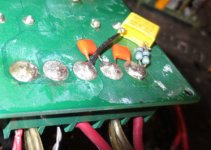
 here you can see the additional 10 uf ceramic caps soldered in to support the floating power supply. I didn't add any to the first cap in that charge transfer chain cause I didn't think it would need it, cause its being fed by a regulated voltage, but it wouldn't hurt to put one on there as well. All three of these caps are sort of in a row. there is another 10uf ceramic cap closer to the end of the board .. it's related to the boards input and doesn't need any support. Also visible here is the feedback loop mod with the 1kohm resistor and delay cap. Notice the blob of solder leading over to the ground post. There was a ground right there so I used it. A short piece of wire may help to get that solder in to place. Be very careful not to get any solder into the hole as noted on the image, and also ... if you accidentally disturb any of those caps near the top of the image you could have a problem. In my case, after one of the mods, a tiny invisible thread of solder connected one of them to another one ( they had been disturbed and I separated them, but an invisible thread of solder remained) the thread sent the board into exclusive positive feedback which turned a transistor permanently on and burned several fuses before I recognized what was up, and eliminated the invisible thread by running the soldering iron through it. Of course, I had to measure in order to know the thread was there)
here you can see the additional 10 uf ceramic caps soldered in to support the floating power supply. I didn't add any to the first cap in that charge transfer chain cause I didn't think it would need it, cause its being fed by a regulated voltage, but it wouldn't hurt to put one on there as well. All three of these caps are sort of in a row. there is another 10uf ceramic cap closer to the end of the board .. it's related to the boards input and doesn't need any support. Also visible here is the feedback loop mod with the 1kohm resistor and delay cap. Notice the blob of solder leading over to the ground post. There was a ground right there so I used it. A short piece of wire may help to get that solder in to place. Be very careful not to get any solder into the hole as noted on the image, and also ... if you accidentally disturb any of those caps near the top of the image you could have a problem. In my case, after one of the mods, a tiny invisible thread of solder connected one of them to another one ( they had been disturbed and I separated them, but an invisible thread of solder remained) the thread sent the board into exclusive positive feedback which turned a transistor permanently on and burned several fuses before I recognized what was up, and eliminated the invisible thread by running the soldering iron through it. Of course, I had to measure in order to know the thread was there)
Last edited:
new output filter capacitor
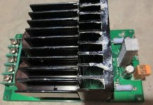
the output filter cap was junk and caused trouble this shows the 0.27 uf cap I replaced it with. It was not the right size, so I ignored one of its holes as you can see and turned the cap on an angle. The second hole only connected the lead of the cap to the ground plane, so I shaved the ground plane with a razor and soldered the second lead straight to the ground plane (after cutting it about 1/8 inch shorter) as you can see. I raised the cap just slightly up over the diode so it wouldn't touch it. The legs were long enough, and the cap didn't poke up higher than the inductor, so it's good. It works
the output filter cap was junk and caused trouble this shows the 0.27 uf cap I replaced it with. It was not the right size, so I ignored one of its holes as you can see and turned the cap on an angle. The second hole only connected the lead of the cap to the ground plane, so I shaved the ground plane with a razor and soldered the second lead straight to the ground plane (after cutting it about 1/8 inch shorter) as you can see. I raised the cap just slightly up over the diode so it wouldn't touch it. The legs were long enough, and the cap didn't poke up higher than the inductor, so it's good. It works
Attachments
the second set of dampeners
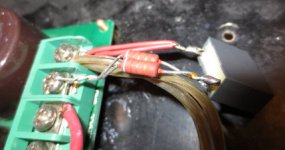
less important than the first dampener, you can see the 0.1 uf cap coupled with a resistance and the two small 0.01 uf caps properly positioned here these caps help kill wigglies that may make it to the power supply rails on the board.
less important than the first dampener, you can see the 0.1 uf cap coupled with a resistance and the two small 0.01 uf caps properly positioned here these caps help kill wigglies that may make it to the power supply rails on the board.
Attachments
the crucial dampener
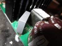
One of two things will happen .. this dampener (cap and resistor connected to the board's output) will kill the parasite, or the parasite will kill the dampeners resistor. I used a pair of 8.2 ohm 2w resistors in parallel and 0.22 uf 275vac (on the order list), the order list shows a 4.7 ohm 5 watt resistor to replace the two 8.2 ohm ones. When you power up the board, keep your eye on that resistor. If it starts to smoke, (could happen in seconds) then immediately power the board down. Or, even better, power the board up with only one lead fastened in, and then touch the lead that goes to the output terminal (right side of the image) .. Hold it for a few seconds.. if the resistor holds without smoking, you're good .. if it doesn't (never had that problem with this version of the dampener, cause this was the winning solution) then there isn't enough dampening, and the parasite is going to destroy that resistor in short order. Disconnect the resistor and power down the board and somehow get around 2.2 ohms, 5 watts between the output filter caps ground lead and ground. Then restart the board, only this time with both dampeners in place. If the resistors don't hold, I would be very surprised. In fact, I would be surprised if this dampener as shown doesn't de-parasite the board.
One of two things will happen .. this dampener (cap and resistor connected to the board's output) will kill the parasite, or the parasite will kill the dampeners resistor. I used a pair of 8.2 ohm 2w resistors in parallel and 0.22 uf 275vac (on the order list), the order list shows a 4.7 ohm 5 watt resistor to replace the two 8.2 ohm ones. When you power up the board, keep your eye on that resistor. If it starts to smoke, (could happen in seconds) then immediately power the board down. Or, even better, power the board up with only one lead fastened in, and then touch the lead that goes to the output terminal (right side of the image) .. Hold it for a few seconds.. if the resistor holds without smoking, you're good .. if it doesn't (never had that problem with this version of the dampener, cause this was the winning solution) then there isn't enough dampening, and the parasite is going to destroy that resistor in short order. Disconnect the resistor and power down the board and somehow get around 2.2 ohms, 5 watts between the output filter caps ground lead and ground. Then restart the board, only this time with both dampeners in place. If the resistors don't hold, I would be very surprised. In fact, I would be surprised if this dampener as shown doesn't de-parasite the board.
Attachments
looking at the reference designs available at IRF
Audio Reference Designs
I cannot find IRAUD200 - and load impedances are specified with 4R at least.
Looks like the specs of these boards are pimped up beyond healthy power ratings.
Audio Reference Designs
I cannot find IRAUD200 - and load impedances are specified with 4R at least.
Looks like the specs of these boards are pimped up beyond healthy power ratings.
There are 2 versions of the board .. 2 ohm and 4 ohm. The 2 ohm version needs all of these mods, including the extra heat sinks to successfully drive 2 ohms. Once the mods are done, it performs like a beast. The IRFB4227 transistor and the larger inductor are the secrets to the 2 ohm version. Make sure your board has the irfb4227 at birth because swapping out those transistors is a dog. The irfb4227 is rated at something like 40 amps .. the cost for that is a high gate charge, which the 2092 chip can only safely drive if you cap it with the small heat sink you see in one of the images, as well as fix the feedback loop as shown so it doesn't try driving it at 800 khz as the board was designed to do. It will chop the frequency response down from 50 khz spec, but who needs 50 khz? Do these mods exactly as shown, and that board will beat the **** out of a 600 watt driver .. even destroy it. When driving only one channel, I smelled burning voice coil on a 600 watt driver some claimed they had driven up to 900 watts into. (no promises on that 900 watt claim for the driver) I'm talking about a 15 inch driver with 2 inch p-p xmax and 260 ounces of magnet. The power supply is capable of delivering 900 watts into a single channel .. wouldn't ask it to do that for both channels. The board just smiled and lauged and said fun, do it again!! The irfb4227 transistors are mean and beastly. Also, for 2 ohm, make sure your copy of the board is rated for 2 ohm and has the larger inductor on it. .. Someone else got a cheap version of the board only to cry over that. I checked the ratings of those inductors, and at audio frequencies they can handle the current, but at switching frequencies they will over heat .. so .. they have to have the heat sinks to dump the extra heat because they are exposed to the switching frequency. Dump the heat with the sink and they will not saturate. One little issue that I haven't tested yet is that the resistor on the (main crucial) dampening circuit might take a beating if you drive a lot of power above 5 khz. Moving to a 7.5 or 10 watt resistor would put that question mark off of the table. I have only used it so far as a sub-woofer driver.
Last edited:
"I cannot find IRAUD200"
I never could either .. but it's all over ebay and amazon and ali-express in various versions .. I suspect most if not all of them will not perform until you get the details right. Infineon is showing an iraudamp9 which sports four irfb4227s, is rated at 1700 watts, and has to use a gate driver setup to drive all of the transistors. The most power you can get out of irs2092 without going to an extra gate driver architecture is the iraud200 driving the irfb4227 (just two of them) and using a heat sink to stay cool. .. and not trying to get 800khz like the stock iraud200 circuit is. The iraud200 board was designed for some crazy reason without the standard delay capacitor in the feedback loop. This will cause the transistor gates to draw probably 30% more current. This is not what we want when trying to drive irfb4227 directly with irs2092. Infineon is asking $400 for their quad irfb4227 board. (iraudamp9) Which is an unrealistic price tag since you can get Behringers new 6kw class D amp for around $400. Thing that bothered me about the Behringer amps is that they were unwilling to say that their amp has short circuit protection in the specs as well as some other protections. The iraud200 board is well protected with short circuit protection, overcurrent protection and overtemp protection. Once you get them working.. they should be the proverbial "bullet proof" I am very happy with these two boards ........ finally .... took six months of occasional attention to figure out the right mods.
I never could either .. but it's all over ebay and amazon and ali-express in various versions .. I suspect most if not all of them will not perform until you get the details right. Infineon is showing an iraudamp9 which sports four irfb4227s, is rated at 1700 watts, and has to use a gate driver setup to drive all of the transistors. The most power you can get out of irs2092 without going to an extra gate driver architecture is the iraud200 driving the irfb4227 (just two of them) and using a heat sink to stay cool. .. and not trying to get 800khz like the stock iraud200 circuit is. The iraud200 board was designed for some crazy reason without the standard delay capacitor in the feedback loop. This will cause the transistor gates to draw probably 30% more current. This is not what we want when trying to drive irfb4227 directly with irs2092. Infineon is asking $400 for their quad irfb4227 board. (iraudamp9) Which is an unrealistic price tag since you can get Behringers new 6kw class D amp for around $400. Thing that bothered me about the Behringer amps is that they were unwilling to say that their amp has short circuit protection in the specs as well as some other protections. The iraud200 board is well protected with short circuit protection, overcurrent protection and overtemp protection. Once you get them working.. they should be the proverbial "bullet proof" I am very happy with these two boards ........ finally .... took six months of occasional attention to figure out the right mods.
You're right about the iraud200 (and iraud350) being some chinese unknown brand, and not being a good design .. works beautifully now though ") Why couldn't the chinese just get it right the first time? Yaknow that's a really good question that we in the west continue to confront with the Chinese stuff that has no western style quality control management.
Why couldn't the chinese just get it right the first time? Yaknow that's a really good question that we in the west continue to confront with the Chinese stuff that has no western style quality control management.
the iraudamp9 looks like an interesting option. ebay offers one from ljm (L30D). My earlier exp. with ljm is that the board (L25D) did not perform as claimed by the seller, but that it did perform for 8 ohms. In the case of L30D, it looks like the heat sink is substantially smaller than that of the iraud200, and the inductor will need a heat sink as well, so I doubt it will be safe with 2 ohms out of the box. That board may have a great chance of working with just heat sink boosting though and successfully drive 2 ohms. I doubt he went crazy like the iraud200/350 folks and eliminated the 150pf 1kohm delay in the feedback as his L25D had it there . .. at least I see a small cap on it with the label 151, which is probably 150 pf. The L25D has dampener caps/resistors built in, so I expect ljm would have followed suit for the L30D Sure electronics is probably a good bet. I didn't find a sure electronics option that matched the amp9 or iraud200 though. Parts-express has those, and there is no match. The specs I wanted required either the iraud200 or the amp9 .. either the two transistor or four transistor version of the amp9 would have worked. However LJMs L30D is only two transistors. In any case, I got what I wanted, it just cost way too much time and extra trouble. If I were to propose a solution to the 600-1000 watt per channel 2 ohms and +/- 70 volt power supply at this point I wouldn't know whether to choose the iraud200 and follow these mods or to be bold and try the L30D that I don't know much about. .. Let people decide on their own I suppose.
Why couldn't the chinese just get it right the first time? Yaknow that's a really good question that we in the west continue to confront with the Chinese stuff that has no western style quality control management. the iraudamp9 looks like an interesting option. ebay offers one from ljm (L30D). My earlier exp. with ljm is that the board (L25D) did not perform as claimed by the seller, but that it did perform for 8 ohms. In the case of L30D, it looks like the heat sink is substantially smaller than that of the iraud200, and the inductor will need a heat sink as well, so I doubt it will be safe with 2 ohms out of the box. That board may have a great chance of working with just heat sink boosting though and successfully drive 2 ohms. I doubt he went crazy like the iraud200/350 folks and eliminated the 150pf 1kohm delay in the feedback as his L25D had it there . .. at least I see a small cap on it with the label 151, which is probably 150 pf. The L25D has dampener caps/resistors built in, so I expect ljm would have followed suit for the L30D Sure electronics is probably a good bet. I didn't find a sure electronics option that matched the amp9 or iraud200 though. Parts-express has those, and there is no match. The specs I wanted required either the iraud200 or the amp9 .. either the two transistor or four transistor version of the amp9 would have worked. However LJMs L30D is only two transistors. In any case, I got what I wanted, it just cost way too much time and extra trouble. If I were to propose a solution to the 600-1000 watt per channel 2 ohms and +/- 70 volt power supply at this point I wouldn't know whether to choose the iraud200 and follow these mods or to be bold and try the L30D that I don't know much about. .. Let people decide on their own I suppose.
Ahh, the marvels of Chinese engineering. I have a similar story for you.
A while back i had a pair of cheap karaoke type active speakers to fix, and after cleaning up the mess that some other tech made of it, i noticed a whistling noise in the speakers, which would come and go depending on the input used, volume level and frequency content.
Something was oscillating, that was obvious. But what... that was not so easy to determine. I checked the amplifier but it did not seem to come from the power amp itself. I then disconnected the tuner (which was replaced by someone else with a module from a Sony stereo), it was better but it still did it sometimes.
Eventually, i traced the problem down not to a faulty part, but to poor design. The supply for the mixer, tuner and all that stuff is made with 7812/7912. Nothing out of the ordinary here. The problem was how they did that.
The regulators were fed by two 100 ohm 3W power resistor from the main filter capacitors. The Chinese guy designing the thing, in his infinite wisdom, thought that because he had the main filter caps there, there was no need for input capacitors to the regulators, but he apparently forgot about the 100 ohm resistors between the caps and the regs... The lack of an adequately low impedance input was causing the 7812 to oscillate, and when a change in power consumption occured, the oscillation would be modulated causing the audible whistle i was hearing in the speakers. Installing some 22uF electrolytic caps between the input and ground pins of the regulators stopped the oscillation and made the speakers sound clean. Well, as clean as some bottom-of-the-barrel chinese sh** can sound, but nevertheless, loads better.
Oh, my story has nothing to do with this board. Sorry for going off-topic.
You are missing the point. They are getting it exactly right for their customers.Why couldn't the chinese just get it right the first time?
The business model does not need a proper design.
Why boosting R&D costs, as long as there are enough ignorants who buy just anything simply because it is cheap and accept low quality?
Why boosting R&D costs, as long as there are enough DIYers who buy just anything simply because it is cheap and then spend months to improve it according personal needs?
Why boosting R&D costs, as long as there are enough DIYers who buy just anything simply because it is cheap and then deliver R&D hints for free?
You are missing the point. They are getting it exactly right for their customers.
The business model does not need a proper design.
Why boosting R&D costs, as long as there are enough ignorants who buy just anything simply because it is cheap and accept low quality?
Why boosting R&D costs, as long as there are enough DIYers who buy just anything simply because it is cheap and then spend months to improve it according personal needs?
Why boosting R&D costs, as long as there are enough DIYers who buy just anything simply because it is cheap and then deliver R&D hints for free?

Yup, but it is not necessarily a bad thing.
Business company and customers seem to be satisfied. What else could one demand?
Only some old fashioned dinosaurs like me do not enjoy this way, but they do not need to buy it.
Publishing learnings for free also is not a bad thing. It is just a personal question whether you feel that it will be used more in a way which you support or more in a way which you do not want to support. Unfortunately this is often difficult to judge and even more difficult to control.
Sorry for off topic discussion. Must stop now, don't want to violate forum rules.
- Status
- This old topic is closed. If you want to reopen this topic, contact a moderator using the "Report Post" button.
- Home
- Amplifiers
- Class D
- iraud200 short story