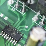
it is unwise to run this board stock. You should not even power it up until you have at least added heat sink grease and a heat sink on the 2092. My best guess is that you have a really bad parasite problem and it's tripping the over-current .. or undervoltage. You are actually lucky your board is doing that. Otherwise you could very easily lose your 2092 chip to overtemperature. Don't power it up again until you get heat sink grease on the transistors and heat sink glue(plaster)/heat sink on the 2092. Just be patient, or you will wind up crying. Next, don't touch the 3.6k resistors until you have also modded the feedback loop and switched the output capacitor and added the dampener circuits. Get to that spot then start asking more questions if the board doesn't work. This board has basically no chance of performing until the mods are done. Might as well fix what we know is wrong first before asking more questions. I don't think your problem is the 3.6k resistor .. more likely the transistors are heating up very quickly from the parasite because you have no grease on them. That will cause their resistance to as much as quadruple or more. The overcurrent protection senses the voltage across the transistor in order to deduce current. Hot transistor = high internal resistance = high current measurement if the parasite is active ... and it almost certainly is. So, what I'm saying is that without greasing the transistors, the parasite all by its self could cause overcurrent tripping. I promise you, that parasite moves quite a bit of current .. it just bounces back and forth between the inductor/capacitor/and power supply .. it doesn't make it to the load, but heats up the transistor something fierce. We're talking about something like 40 to 100 watts, which will sear the bare transistor in seconds.
I never even tried running this thing without heat sink grease/heat sink on the 2092 (stock), so perhaps you are showing us what happens when you do that. You are lucky something or other didn't blow. It may be wise to double check the resistance across the two main transistors just to be sure the transistors are ok. If they are bad, then you'll be able to measure a short between two or more legs of the same transistor. I don't think you lost them though, or the result would be more violent. I thought I adequately warned people of trying to run this board stock.
To all others reading this thread .... do not run this board stock with no heat sink grease on the transistors/heat sink on the 2092. Not even once. Just don't do it.
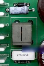
Check the temperature of the output transistors themselves, not the heat sink, as the transistors are not coupled to the heat sink without grease. If your output cap is 0.47 and 200v plus, it should be fine. 100v might even work if there is no parasite. Also, if you want high frequency output ... guess what ... you have an additional problem. The 200k resistor in the feedback loop is too high. It is too weak of a connection between the 2092 input and the transistor outputs. The weak connection allows ambient e-m fields to mess with the 2092 inputs. .. and you get hum. I haven't solved this yet because I'm using mine for sub-woofers. One option would be to drop the 200k resistor to 120k and feed the board a stronger input signal. Otherwise, swapping out the 200k for 120k will require another resistor to also be swapped in order to maintain the gain factor, and I haven't looked it over yet for how that solves. The safe easy bet is to swap the 200k for 120k and drive the board harder. That will kill some of the hum.
Last edited:
If the output transistors are not getting hot, then your board may be so different from mine that it's hard to help you. I'm already guessing that you may have the 4 ohm version .. your transistors may not be irfb4227. the hint at yours being the 4 ohm version would be the 0.47 uf cap. I think the 1 uf cap was introduced with the idea of driving 2 ohms.
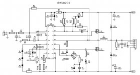
I never could dig up a schematic for the iraud200. It is very similar to the reference designs except 1: they mistakenly removed the 1k and 150pf delay components from the feedback loop 2: they mistakenly used 200k and 5.1k resistor pair for the gain definition .. ... 3:they included an overtemp element in the power supply for the gates .. cuts all gate power when hot ... very nice 4: they mistakenly removed the dampening resistors/caps 5: they removed the dc blocking cap from the input and replaced it with a 1nf 2k rc filter to filter out high frequencies. For some reason they wanted 0-50khz response, which doesn't make a lot of sense, but DC could potentially be useful. However, actually running DC could cause a really bad bus pumping problem. Haven't tried it, but say 40v dc output could wind up pumping the extra power onto the other rail ... ouch!!!!!! 6:They used irfb4227 (high power, but huge gate charge) so they removed the gate resistors ... this causes a requirement for heat sinking the irs2092 chip. 7:some versions of this are coming with 1uf output filter cap in stead of 0.47 uf output cap ... this appears to be another mistake .. some versions mistakenly are using 100v output cap .. I'm looking at one on ebay that is correctly using 250v and 0.47uf.
Without pains, I can't currently get info. regarding the resistors used for overcurrent detection.
At this point in time, I believe that moving back to 120k and 3.1k resistors in the feedback loop would be wise ... this should kill the 60 hz hum receptivity of the board.
Without pains, I can't currently get info. regarding the resistors used for overcurrent detection.
At this point in time, I believe that moving back to 120k and 3.1k resistors in the feedback loop would be wise ... this should kill the 60 hz hum receptivity of the board.
My excursion into the irs2092 was very painful.
It took 3 revisions of pcb to get one that worked.
1/ Decoupling close to 2092 and output mosfets is vital.
2/ Tight pcb layout is required.
3/ The OC resistors need to be desensitised to stop resetting.
4/ In my experience 4227's need gate drivers although I have heard of people getting away without them.
I also had a problem with power down causing a one second siren type noise followed by a huge thump through speaker. IR said it was due to my using too much smoothing capacitance. I put together a simple PIC with A2D that monitored VCC and when it fell low it used a opto coupler to turn off reset.
Nigel, a simple loudspeaker protection could solve many shutdown issues, irfb4227 need certainly a gate drivers to work best, but for 500watt (more than enough for every diyer) the market is full of low Qg mosfets.
Graygem I realized it was not your design, but from what I see in the schematic the operation will be horrible, the usual Chinese copy, no R&D, no selection in the components, if it does work badly otherwise you wasted your money.
Graygem I realized it was not your design, but from what I see in the schematic the operation will be horrible, the usual Chinese copy, no R&D, no selection in the components, if it does work badly otherwise you wasted your money.
The PIC solution was pretty simple.Nigel, a simple loudspeaker protection could solve many shutdown issues, irfb4227 need certainly a gate drivers to work best, but for 500watt (more than enough for every diyer) the market is full of low Qg mosfets.
I just used a small PIC with A2D on board.
Output was to a small cheap opto-isolator.
Power supply dropped from B+ using a resistor and zener.
I didn't want to use a relay.
The problem with 4227's is the gate capacitance. What happens is the gate doesn't charge fast enough for the 4227 to switch on before OC cuts in.
If you use small enough gate resistor that it works ok the 2092 is driving the 4227's too hard.
I used either TC4420 or push/pull transistor pair to drive the 4227 gates.
Last edited:
- Status
- This old topic is closed. If you want to reopen this topic, contact a moderator using the "Report Post" button.
- Home
- Amplifiers
- Class D
- iraud200 short story


