I hope this is the right board for this question.
I'm trying to power the amp and the MCU/DSP/DAC off a single 19V power supply and I'm getting a lot of digital squawlking kind of noise out through the amp. I don't have this problem if I take this identical configuration (including smps) but instead power the amp off a separate power supply (two wall warts). Unfortunately I need only one cord to the wall for this embedded project. Is there something simple I'm missing to cancel out the noise? Any help is appreciated.

I'm trying to power the amp and the MCU/DSP/DAC off a single 19V power supply and I'm getting a lot of digital squawlking kind of noise out through the amp. I don't have this problem if I take this identical configuration (including smps) but instead power the amp off a separate power supply (two wall warts). Unfortunately I need only one cord to the wall for this embedded project. Is there something simple I'm missing to cancel out the noise? Any help is appreciated.
Last edited:
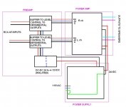
The SMPS output is referenced to the 19V GND! I would have both come of the SMPS with twisted pair cable and probably a ferrite on output.
Can you explain that a little more for me I'm thick skulled
")
so the 5V line and it's ground should go through some sort of inductor coming out of the smps
lately i've replaced all the caps with 100nF local decoupling across the power for the arduino and codec board with a 2200uF bulk across the 19V source. I've also tried adding 10uF across the in and out of the SMPS as suggested for additional filtering by it's datasheet. Still the same old noise that sounds related to the clock from the MCU.
Would running the audio lines through some 1:1 transformers work in a pinch? I'm on a tight deadline
Adding 2200uF on the output of a regulated SMPS probably isn't a good idea.
Have you tried a linear reg for the 5V supply? Powering a switching supply from a switching supply seems like a recipe for noise. Might also try a low value resistor in series with 5V SMPS if you don't have a linear reg.
Have you tried a linear reg for the 5V supply? Powering a switching supply from a switching supply seems like a recipe for noise. Might also try a low value resistor in series with 5V SMPS if you don't have a linear reg.
Adding 2200uF on the output of a regulated SMPS probably isn't a good idea.
Have you tried a linear reg for the 5V supply? Powering a switching supply from a switching supply seems like a recipe for noise. Might also try a low value resistor in series with 5V SMPS if you don't have a linear reg.
the 2200uF is actually over the 19V supply which I got from a linear reg circuit plan. I don't very well understand how it works though, curious what would make it wrong out of the smps?
I've tried swapping the SMPS for a 7805 but no change in sound. This SMPS is supposed to be a drop in replacement for a 7805.
I've actually just fixed this problem now by placing a cheap 1:1 transformer over the audio lines.
I've actually just fixed this problem now by placing a cheap 1:1 transformer over the audio lines.
This is a strong indication that your problem was some kind of ground loop, i.e. bad wiring.
This is a strong indication that your problem was some kind of ground loop, i.e. bad wiring.
voltwide is right. From the diagram it's pretty obvious to me it's a ground loop issue. This is a pretty common issue when using a common supply between units that are also passing a signal. You need a ground capable of handling the supply currents and you need a ground next to your signals to keep the signal quiet, but the result is a big loop. Kinda a catch 22. There are lots of ways of dealing with it. Best solution is to break the ground loop. I've used isolated 5V DC-DC POLs similar to what you have and that works pretty good. In a pinch you can try to reduce/suppress the noise by decreasing the loop as much as possible. Sometimes this can be done by simply moving the wire routing or making a star ground as JonSnell suggested. You can also try to reduce noise currents by adding impedance to the noise path. Strategically placed resistors or inductors/ferrites can work.
Also adding more ground connections with thick wire to bypass the loop, a common fix for such EMC problems, many commercial boards often have a nice big hole to solder some nice thick cable between boards to solve this issue.
I haven't seen that before. Is this like using a mesh ground (as opposed to a star ground)? Any links you can provide detailing the method?
I haven't seen that before. Is this like using a mesh ground (as opposed to a star ground)? Any links you can provide detailing the method?
Here's stuff related to audio directly...
Tony Waldron's EMC ranting and ravings
The adding holes to boards has been done for 30+ years to my knowledge and is still done today to many designs it is common practice and a get out of jail free card when ground loop problems occur, usually caused by lower frequency signals finding a lower resistance return path than the route the engineer/designer thought they were going to take...
Don't forget what Horowitz and Hill say about star grounds in the Art of Electronics....
Higher frequency noise is usually caused by stray capacitive coupling....
Here's the assembly.

the chassis will be a MDF speaker cabinet.
The bandwidth of the transformer is okay for the application luckily. I might order a slightly better one. I'm a bit confused, this transformer is supposed to be 1k primary/8 sec ohm impedance. Online I'm looking at a 600/600 and a 10k/10k. Is there a significant effect of the difference in impedances.
Thank you again everyone this is very informative
...
I've used isolated 5V DC-DC POLs similar to what you have and that works pretty good.
...
I have as well. Also used isolated +/- 12 for SE to diff amp.
Then the signal gnd only comes from the amp.
Attachments
Here's stuff related to audio directly...
Tony Waldron's EMC ranting and ravings
The adding holes to boards has been done for 30+ years to my knowledge and is still done today to many designs it is common practice and a get out of jail free card when ground loop problems occur, usually caused by lower frequency signals finding a lower resistance return path than the route the engineer/designer thought they were going to take...
Don't forget what Horowitz and Hill say about star grounds in the Art of Electronics....
Higher frequency noise is usually caused by stray capacitive coupling....
Thanks for the link. I've actually read that page before. Probably where I heard of mesh type grounding before, I've just never seen it implemented in an electronics box. I'll have to give it a try. Any suggestions on implementation? How many holes are we talking about? What kind of wire gages?
Online I'm looking at a 600/600 and a 10k/10k. Is there a significant effect of the difference in impedances.
I'm no expert on transformers, but I think you want to use as low an impedance as the source is comfortable driving so that the output impedance is also as low as possible.
Some can correct me if I'm wrong.
Is that an electrolytic I see on the output of the SMPS module... if so ditch it for a small SMD size 10uF Ceramic cap....
All wire pairs I would twist together to form intimate and smaller loops, it will all help.
Isn't this a bit to generic? MLCCs aren't the mighty helper for all problems.
- Status
- This old topic is closed. If you want to reopen this topic, contact a moderator using the "Report Post" button.
- Home
- Amplifiers
- Class D
- Picking up too much digital noise with TPA3116