I had the very same experience.i find the tda8932 some kind of 'easier' to listen to. I mostly listen to old reggae and dub stuff which is very bassy.
atm i prefer the stock tda8932 which is a perfect match for that stuff and my visaton bg20's. the311x sometimes seems a bit 'shouty' especially for higher male voices.
There's a plentiful variety of amplifers available so that it is okay to choose one that is easier to listen to (more relevant output).
Although the majority of TDA8932 applications are pleasant-tone mid-fi, it is also true that high fidelity capacity exists, at higher resolution, with exactly the same pleasant/relevant tone, and the same chip. That is a grand surprise! We may be in need of a new board that more thoroughly exploits the Audio capacity of the TDA8932.
I made a 2.1 version with one single chip, for fun, of course. It has been both more durable and higher resolution than expected.
Hello. I have seen those really cheap amps on aliexpress and I have a question. Can something like this drive a Markaudio chr-70 at full power even if it does not have a radiator?
http://g02.a.alicdn.com/kf/HTB1OAM2...ule-Mono-Power-Amplifier-Module-AMP-Power.jpg
http://g02.a.alicdn.com/kf/HTB1OAM2...ule-Mono-Power-Amplifier-Module-AMP-Power.jpg
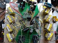
Kudos for exploring that.Here's the latest development with my SanAi modules - stacking a pair in series. I've wound 4 trafos per channel but here I'm using them in paralleled pairs just to test the concept. Promising
However, it would be nice if you'd reduce the number of transformers required.
Even so, the photo of that thing is awesome! I'm certainly not doing it that way, but I did like the photo!
Here's the latest development with my SanAi modules - stacking a pair in series. I've wound 4 trafos per channel but here I'm using them in paralleled pairs just to test the concept. Promising
Cool experiment. I missed the boat on the SanAi module. Is there a link or a photo of one without all the embellishments?
I do think that the Sanwu module I have sounds similar to my class A ACA amp but with gobs more power. Very transparent and perhaps bass is even better than ACA?
However, it would be nice if you'd reduce the number of transformers required.
It might be possible to arrange it to just need one transformer, using four primaries. The reason I've done it with four is because I'm too lazy to count turns accurately - having the primaries on different trafos means the ratios are none-too-critical. Four primaries would need to be identical numbers of turns not to fight each other, even then the gains would need tweaking as the DS only says they're within 1dB which is a pretty huge margin in the scheme of things.
@xrk The module doesn't show up on Taobao when searching for TDA8932, rather you have to search on 'TDA2030A' for it to appear - https://item.taobao.com/item.htm?spm=a230r.1.14.176.4DhAyZ&id=21834236177&ns=1&abbucket=13#detail
By the way in case anyone's wondering, the little PCB in the middle is to generate a common clock for all the modules - the DS says there's noise from the on-chip clock osc at higher voltages and this is designed to run up to the maximum voltage of the supply caps (35V).
Last edited:
Abrax'o,
Thanks for the link. I have an Aliexpress account all set up so hope to find it there but no luck. Is this module better sounding than Sanwu? I don't have any clock issues on Sanwu.
Price seems to have gone up!? With all the rave reviews the demand has gone up? They used to be circa $3ea everywhere and now most vendors in the $5 range.
Online Shop 35W TDA8932 Digital Amplifier Board Module Mono Low Power Stereo Amplifier|Aliexpress Mobile
I have only played with this one so can't comment on its SQ vs any of the others. The primary reason I like it is the ease of replacing the SMT cap with a through-hole one.
I have the original Aliexpress link on my blog - when I first found it it was $7.46, now this link shows a reduction to $5.98 TDA2030A 35W High Power HiFi Mono Digital Amplifier Board Ultra Low Power AMP-in Amplifier from Consumer Electronics on Aliexpress.com | Alibaba Group
I have the original Aliexpress link on my blog - when I first found it it was $7.46, now this link shows a reduction to $5.98 TDA2030A 35W High Power HiFi Mono Digital Amplifier Board Ultra Low Power AMP-in Amplifier from Consumer Electronics on Aliexpress.com | Alibaba Group
I have only played with this one so can't comment on its SQ vs any of the others. The primary reason I like it is the ease of replacing the SMT cap with a through-hole one.
I have the original Aliexpress link on my blog - when I first found it it was $7.46, now this link shows a reduction to $5.98 TDA2030A 35W High Power HiFi Mono Digital Amplifier Board Ultra Low Power AMP-in Amplifier from Consumer Electronics on Aliexpress.com | Alibaba Group
Oh you have an Ali link! Thanks!
Can I see a closeup photo of your board? It looks like you stacked inductors?
Do you have a low cost source of input trafos on Ali by chance? They are so darned expensive elsewhere...
I will take a close-up photo later for you. Yes I stacked inductors because I didn't have the correct value (140uH in the large size) so I paralleled 5 * 680uH of 7mm diameter which I have a whole reel of. I needed a different output filter as with the output transformers, there's a multiplication of the speaker impedance.
As for the input trafos, I make them myself. In fact I've replaced the ones in that picture with some made from EP17 cores which are physically smaller (17mm on a side cubes). To make those you'll benefit from a winding machine, the turns number is 2400 for the primary and the secondary is 500 turns, centre tapped. I used 0.07mm wire.
I just had a search on Aliexpress, they're not showing anyone selling EP17 but there are plenty of vendors with RM8 which is a little larger, hence will need fewer turns. Prices are about $2 for a core set. Taobao is even cheaper but there shipping's not included.
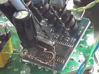
Here's a highly zoomed-in shot of one of my modded boards.
Points of note - I'm running twisted pair differential input from the EP17 transformer, there are 11k resistors in series to attenuate HF pickup. Two extra caps added for decoupling, one to the analog power supply (pin8) and one on the analog Vref (pin12). Pin12 goes to the trafo CT allowing deletion of the input caps. Pin10 (resistor osc frequency setting) is 0R to GND because I'm using an external oscillator.
Points of note - I'm running twisted pair differential input from the EP17 transformer, there are 11k resistors in series to attenuate HF pickup. Two extra caps added for decoupling, one to the analog power supply (pin8) and one on the analog Vref (pin12). Pin12 goes to the trafo CT allowing deletion of the input caps. Pin10 (resistor osc frequency setting) is 0R to GND because I'm using an external oscillator.
Attachments
I will take a close-up photo later for you. Yes I stacked inductors because I didn't have the correct value (140uH in the large size) so I paralleled 5 * 680uH of 7mm diameter which I have a whole reel of. I needed a different output filter as with the output transformers, there's a multiplication of the speaker impedance.
As for the input trafos, I make them myself. In fact I've replaced the ones in that picture with some made from EP17 cores which are physically smaller (17mm on a side cubes). To make those you'll benefit from a winding machine, the turns number is 2400 for the primary and the secondary is 500 turns, centre tapped. I used 0.07mm wire.
I just had a search on Aliexpress, they're not showing anyone selling EP17 but there are plenty of vendors with RM8 which is a little larger, hence will need fewer turns. Prices are about $2 for a core set. Taobao is even cheaper but there shipping's not included.
Abrax'to,
Are thes cores ok for rolling your own?
5set New EP17 4 4PINS Ferrite Cores Bobbin Transformer Core Inductor Coil | eBay
I am trying to make a unbalanced to balanced trafo for the input stage of a JFET input on a Circlophone class A.
The preamp driving it has lots of power and the input impedance of the JFET is high but can be anything. How do I calculate what dia wires and how many turns etc?
Let's say I want 60ohm inputs (like head phones) and 120ohm balanced outputs. Can I reduce the number of windings significantly?
The preamp driving it has lots of power and the input impedance of the JFET is high but can be anything. How do I calculate what dia wires and how many turns etc?
Let's say I want 60ohm inputs (like head phones) and 120ohm balanced outputs. Can I reduce the number of windings significantly?
I am trying to make a unbalanced to balanced trafo for the input stage of a JFET input on a Circlophone class A.
The preamp driving it has lots of power and the input impedance of the JFET is high but can be anything. How do I calculate what dia wires and how many turns etc?
Let's say I want 60ohm inputs (like head phones) and 120ohm balanced outputs. Can I reduce the number of windings significantly?
X 60 ohms as input is low, has to be minimal 600 ohms if you want to connect on cd or such, therefore 2400 windings are sufficient?, I need the core permiability for it, AL value, because it is ferrite and looks it is a puls transformer I do not now how wide it go, do need a airgap to prevent saturation.
did see that nickel permaloy is the way to go.
regards
Yes those are precisely the same as the ones I'm using as far as I can tell.
My trafos are designed to handle a full-scale input signal of 2VRMS, if you work with different levels you might need fewer (or more) turns and hence perhaps a different diameter wire.
Nice thread, because this is what a lot of people do seek, however is ferrite the stuff to use because of distortion?.
regards
The preamp driving it has lots of power and the input impedance of the JFET is high but can be anything. How do I calculate what dia wires and how many turns etc?
Transformer design is primarily about Volt-seconds. The maximum product of Volts and seconds occurs at full-amplitude of the lowest frequency you want the trafo to pass. The cross-sectional area of the core of the transformer determines the number of turns needed, per volt, given the lowest permissable frequency.
Typically 60ohm headphones need under 1VRMS (its the voltage which is important, not the impedance primarily for trafos) for ear-splitting levels so that would allow you to halve the number, straight off the bat. My MSR7s (admittedly 35ohms) would be excruciatingly loud at 1VRMS so perhaps given only the 60ohm spec you could go even fewer in turns. Reducing the input turns by a factor of two doesn't affect the output turns number as that's determined by the clip level of the TDA8932.Let's say I want 60ohm inputs (like head phones) and 120ohm balanced outputs. Can I reduce the number of windings significantly?
Last edited:
X 60 ohms as input is low, has to be minimal 600 ohms if you want to connect on cd or such, therefore 2400 windings are sufficient?
2400 was determined empirically by sending a 20Hz 2VRMS sinewave through the trafo and looking to see where distortion started to appear on the 'scope. If the CD player's output level is the standard 2V you'll be fine with 2400 turns.
I have two kinds of cores for my EP17s - one normal, one high mu. The high mu one can't handle so much flux so it needs more turns (about 30% more) than the normal one (probably PC40 material, that's the most common type here)., I need the core permiability for it, AL value, because it is ferrite and looks it is a puls transformer I do not now how wide it go, do need a airgap to prevent saturation.
Ferrite cores can easily be air-gapped, but I'd not advise that for transformers, generally we want the highest shunt inductance to present the lightest load to the source. Without an air gap, when the trafo's correctly designed it will only saturate when taken beyond its design limits (in Volt-second terms) so an air-gap is by no means essential.
Abraxalito,
That would be great if you can show us step by step how to spec and roll an input trafo - a how to thread would be most beneficial. Many people would like to be able to make their own I think if it's a matter of labor to wind. Maybe a drill motor and spool tension holder?
Regards,
X
That would be great if you can show us step by step how to spec and roll an input trafo - a how to thread would be most beneficial. Many people would like to be able to make their own I think if it's a matter of labor to wind. Maybe a drill motor and spool tension holder?
Regards,
X
I'll look into this then, and search eBay to see if there are any suitable winding machines. A drill works (I've used a small DC powered 'Dremel'-style one myself) but doesn't have the facility to count turns which is normally a fairly important feature to have. Without a turns counter it takes trial and error (a fairly drawn-out process) to get into the right ballpark number of turns.
- Home
- Amplifiers
- Class D
- Fasten seat belts. TDA8932 pessimistic review.