Sorry buddy. I didn't mean to say that you'd purchased a poorly amplifier. That's not the case at all.
(...)
No worries! My silence on the subject is simply due to lack of time to play with them.
") And looking into the future, it might be a while before I actually get a chance to see what they're all about. Also, if nothing else, I'm waiting on that $11 SMPS to be delivered.
And looking into the future, it might be a while before I actually get a chance to see what they're all about. Also, if nothing else, I'm waiting on that $11 SMPS to be delivered.I did read all the previous posts, including the T vs BT discussion. I mostly ignored that when I bought these modules, as I was attracted to the convenience of pre-existing through-holes for balanced inputs.
And even if they turn out to be a total dud, it's a $12 mistake I can live with. For me, much (most?) of the fun comes from the process rather than the result. At least half my motivation is, quite literally, just something to play with.
Thanks guys for your reviews, just ordered two "blue" boards. I have a question, is it possible to "unlink" one of this boards, and use it as stereo amplifier, so I will get 2.1 sound with two of these boards (one operating subwoofer, and another one operating stereo speakers?)
You can't convert from a board designed as a PBTL without more real estate for more inductors and caps I think. PBTL uses half the output filter components. Agree that they cost nothing ($3 and change) and getting more channels is the way to go.
Some amps like the SMAKN TPA3116 are designed as BTL but with jumpers to convert to PBTL, they can switch easily between the two modes as all the parts needed are already on-board.
Some amps like the SMAKN TPA3116 are designed as BTL but with jumpers to convert to PBTL, they can switch easily between the two modes as all the parts needed are already on-board.
x, you are mixing things up.
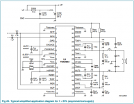
TDA8932 chips can be driven either in SE (single ended, stereo) or BTL (bridge, mono) modes.
compare fig 36 and 37 from the ds:
http://www.nxp.com/documents/data_sheet/TDA8932B.pdf
TDA8932 chips can be driven either in SE (single ended, stereo) or BTL (bridge, mono) modes.
compare fig 36 and 37 from the ds:
http://www.nxp.com/documents/data_sheet/TDA8932B.pdf
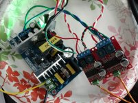
Looking closely, the amp on the right is using the older TDA8932T, that on the left has the updated TDA8932BT. From the datasheets the difference I noticed is that the newer 'B' suffix part has 1Mohm resistors integrated on the chip - the older (no 'B') part needs those 1Mohm resistors fitted on to the PCB. But the board is clearly laid out for the 'B' part as those resistors are nowhere to be seen.
You could try adding 1Mohm resistors (across the 15nF bootstrap caps, between pins 21/22 and 27/28) to the amp on the right and see if that helps with the SQ in BTL.
did anybody try this?
! Digitale platinenmodul 35 watt mono verstrkermodul High power TDA8932 geringer stromverbrauch in Hinweis: die neue Spurhaltungszahl fr China-Pfosten Gewhnliche Kleine Packet Plus nur knnen es haben Schiff aus Ch aus Integrierte Schaltungen auf
i contacted the vendor and he said that he solely has amps with the "BT" print in stock.
i don't know why, but i ordered two more.
i contacted the vendor and he said that he solely has amps with the "BT" print in stock.
i don't know why, but i ordered two more.
Finally got mine wired up for testing. Just started listening but initial impression is good. I'm driving single full range drivers, and I don't hear any obvious high frequency stuff Daniel mentioned. Though in general I'm starting to think my ears are the biggest limiter in my system.
Anyway. You can see I'm using a 24V SMPS, that was just over $10 from Ebay. The rest of the parts were all recycled. For about $20 total invested, it's definitely a good value. My upstream source is single-ended, so I'm currently using what I believe is called a pseudo-differential cable (cold signal is shorted to ground).
Next step will be to put an unbalanced-to-balanced transformer in between to feed these guys a truly balanced signal. (Also working on upgrading the DAC to truly balanced.)
This has been hinted at in this thread before, but I'm really surprised how hot these chips run. I can't keep my finger on them for more than a few seconds. My IR thermometer says the tda8932 package temp is about 35C. The inductors don't feel as warm (can keep my finger on them comfortably) but the IR thermometer says 55C!
Do you think using a thermal pad between the bottom of the PCB and a metal case would help bring the temps down?
Listening as I type this, I think I could live happily with this amp. There were some mods mentioned for the power supply in another thread that I'll do, and we'll see what a truly balanced signal will do.
I think it's definitely worth fitting it all in a case.
Side comment: Daniel, you titled this thread "pessimistic". The overall tone I'd argue is closer to optimistic IMO.
Attachments
I was so surprised! These chips are capable of a rather wide variety.Daniel, you titled this thread "pessimistic". The overall tone I'd argue is closer to optimistic IMO.
The TDA8932T bridged for even worse treble quality, does get me pessimistic.
However, they can perform well on fidelity and even run cooler, only if used in SE mode.
The TDA8932BT (and cooler TDA8932BTW) run single ended (or at least the tweeter using the single ended output), does get me optimistic, and probably even enthusiastic.
Heatsink as large as the boards, does bring down the temps. But, I didn't need that, because I needed what SE mode does.Do you think using a thermal pad between the bottom of the PCB and a metal case would help bring the temps down?
Last edited:
I've been running some experiments with this chip. I wanted to know if the chip itself has some limitation on SQ or if the issues of HF quality I've had with it are really down to the less than perfect power supply. So I listened to a pair of my SanAi boards (modded as per my post back in Jan) with as light a load as I could manage, which was my DT880s fed via 3:1 step down transformers. The effective load here is of the order 5kohms - on listening I couldn't be sure I could distinguish these chips from my classA balanced SE amp. Which means the chips themselves, they're as transparent as I need - all the relevant SQ issues are then about how good (by which I mean low impedance) a power supply can be attached to them.
I'm now running a pair full range (with output step down trafos of 2.5:1) into my passive speakers (Paiyons) and 'gob-smacked' gets closest to how great they're sounding. I've found I need 3 paralleled Nichicon 1500uF/35V caps on the rails to reach nirvana.
I'm now running a pair full range (with output step down trafos of 2.5:1) into my passive speakers (Paiyons) and 'gob-smacked' gets closest to how great they're sounding. I've found I need 3 paralleled Nichicon 1500uF/35V caps on the rails to reach nirvana.
Various random thoughts/questions...
Anyone try this yet? I'm thinking about it, but simple question: could I get away with stacking a 1M SMD resistor right on top of the 15nF? That seems doable, just not sure if I can do it quickly enough to avoid damaging the cap. These SMD resistors are small enough that I could also probably solder directly to the 8932 chip pins. Or a third option, I could instead use a through-hole resistor and cut the leads down pretty short and solder to the cap's pads (similar to SMD stacking but maybe easier to solder?)...
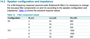
Has anyone tried messing with the output filter at all? Maybe some of the high frequency quality issues that have been observed are due to mis-matched filter-speaker effects. Below, I attached the recommended filter values table from the datasheet. The red boards I have came with 22uH inductors, and default to BTL mode, so I'm thinking they were intended for 8-ohm speakers. Judging from the pics in this thread, that filter appears to be the norm for all these boards. So, for example, switching from BTL to SE mode as Daniel is doing, but keeping the filter the same changes the filter to be optimized for a 4-ohm load. If the speakers are 8-ohm, that means the filter will be either over-dampened or peaking (I forget which). I would assume there is a similar phenomenon at play when Abraxalito puts the transformer between the amp and speakers (i.e., increasing speaker impedance changes the output filter in one direction or the other).
Also, looking at the example BTL circuit (datasheet page 36, attached below), the two inputs are paralleled (IN1P+IN2P, IN1N+IN2N). Just by looking at the pictures in this thread, I don't see traces for that parallel connection. Perhaps the connection is at a different layer than is visible in the pictures? I don't have the boards in front of me now, so can't check with a DMM. If the inputs aren't paralleled, is the board truly running in BTL mode?
Regarding the heat: I recall reading a handful of people in the big tpa3116 thread complaining about hot chips and/or inductors. This was always on the cheap Chinese boards, and IIRC it was at least in some cases due to parts of the reference circuit being omitted (e.g. snubber circuit). And/or (again from my sketchy memory) heat could be improved by using better quality parts, e.g. better inductors. Quality components (inductors in particular) are expensive (at least when buying in small lots from authorized distributors), and when these things can be delivered from the other side of the planet for less than the cost of lunch, something doesn't add up!
I was surprised to see how warm this chip runs... I've run the exact same setup (power supply, speakers, listening level) with numerous tpa311x amps, and they are barely warm to the touch. Even when I run the tpa3116 louder on lower-impedance speakers it is still "touch friendly". Though the tda8932 is relatively older, maybe it's simply less efficient due to older manufacturing tech?
But on the other hand, I was testing this on 85ish dB speakers nearfield, at modest levels (certainly under 80 dB)... so quick math says I'm putting 1W or less into each speaker... even my tda7297 class AB chipamp doesn't get warm on this load. (I've always wondered if I could power my desktop rig with a gerbil running on a wheel.)
I'm under the impression that Class D amps are particularly sensitive to power supply quality. At least that is my hearsay-based perception of the subjective crowdspeak in the tpa311x thread. Seems reasonable, though---is better power ever a bad thing? Anyway, to my ears, putting OS-CON caps on the cheap tpa311x boards always brought a noticeable improvement. So that's the first mod I intend to do to these tda8932 boards: lose the probably dubious-quality electrolytics and replace with OSCON. I'm also going to do some mods to the cheap SMPS I'm using that were mentioned in the tpa3118 thread (BTW these mods are backed by the o-scope measurements Jensen567 did in the tpa3118 thread).
I'm also toying with the idea of shelling out for some better inductors to see if that brings the temps down at all. I'm also thinking about using a heat pad (ala Gmarsh Wiener tpa3118 board) or some RTV silicon (ala xrk971) to mate the boards to a bigger chunk of metal. (But I still think these guys should run cooler in my setup where I don't need a lot of power.)
You could try adding 1Mohm resistors (across the 15nF bootstrap caps, between pins 21/22 and 27/28) to the amp on the right and see if that helps with the SQ in BTL.
Anyone try this yet? I'm thinking about it, but simple question: could I get away with stacking a 1M SMD resistor right on top of the 15nF? That seems doable, just not sure if I can do it quickly enough to avoid damaging the cap. These SMD resistors are small enough that I could also probably solder directly to the 8932 chip pins. Or a third option, I could instead use a through-hole resistor and cut the leads down pretty short and solder to the cap's pads (similar to SMD stacking but maybe easier to solder?)...
Has anyone tried messing with the output filter at all? Maybe some of the high frequency quality issues that have been observed are due to mis-matched filter-speaker effects. Below, I attached the recommended filter values table from the datasheet. The red boards I have came with 22uH inductors, and default to BTL mode, so I'm thinking they were intended for 8-ohm speakers. Judging from the pics in this thread, that filter appears to be the norm for all these boards. So, for example, switching from BTL to SE mode as Daniel is doing, but keeping the filter the same changes the filter to be optimized for a 4-ohm load. If the speakers are 8-ohm, that means the filter will be either over-dampened or peaking (I forget which). I would assume there is a similar phenomenon at play when Abraxalito puts the transformer between the amp and speakers (i.e., increasing speaker impedance changes the output filter in one direction or the other).
Also, looking at the example BTL circuit (datasheet page 36, attached below), the two inputs are paralleled (IN1P+IN2P, IN1N+IN2N). Just by looking at the pictures in this thread, I don't see traces for that parallel connection. Perhaps the connection is at a different layer than is visible in the pictures? I don't have the boards in front of me now, so can't check with a DMM. If the inputs aren't paralleled, is the board truly running in BTL mode?
Regarding the heat: I recall reading a handful of people in the big tpa3116 thread complaining about hot chips and/or inductors. This was always on the cheap Chinese boards, and IIRC it was at least in some cases due to parts of the reference circuit being omitted (e.g. snubber circuit). And/or (again from my sketchy memory) heat could be improved by using better quality parts, e.g. better inductors. Quality components (inductors in particular) are expensive (at least when buying in small lots from authorized distributors), and when these things can be delivered from the other side of the planet for less than the cost of lunch, something doesn't add up!
I was surprised to see how warm this chip runs... I've run the exact same setup (power supply, speakers, listening level) with numerous tpa311x amps, and they are barely warm to the touch. Even when I run the tpa3116 louder on lower-impedance speakers it is still "touch friendly". Though the tda8932 is relatively older, maybe it's simply less efficient due to older manufacturing tech?
But on the other hand, I was testing this on 85ish dB speakers nearfield, at modest levels (certainly under 80 dB)... so quick math says I'm putting 1W or less into each speaker... even my tda7297 class AB chipamp doesn't get warm on this load. (I've always wondered if I could power my desktop rig with a gerbil running on a wheel.
)I wanted to know ... if the issues ... are really down to the less than perfect power supply... all the relevant SQ issues are then about how good (by which I mean low impedance) a power supply can be attached to them.
I'm now ... 'gob-smacked' ... to how great they're sounding. I've found I need 3 paralleled Nichicon 1500uF/35V caps on the rails to reach nirvana.
I'm under the impression that Class D amps are particularly sensitive to power supply quality. At least that is my hearsay-based perception of the subjective crowdspeak in the tpa311x thread.
Seems reasonable, though---is better power ever a bad thing? Anyway, to my ears, putting OS-CON caps on the cheap tpa311x boards always brought a noticeable improvement. So that's the first mod I intend to do to these tda8932 boards: lose the probably dubious-quality electrolytics and replace with OSCON. I'm also going to do some mods to the cheap SMPS I'm using that were mentioned in the tpa3118 thread (BTW these mods are backed by the o-scope measurements Jensen567 did in the tpa3118 thread).I'm also toying with the idea of shelling out for some better inductors to see if that brings the temps down at all. I'm also thinking about using a heat pad (ala Gmarsh Wiener tpa3118 board) or some RTV silicon (ala xrk971) to mate the boards to a bigger chunk of metal. (But I still think these guys should run cooler in my setup where I don't need a lot of power.)
Attachments
Anyone try this yet? I'm thinking about it, but simple question: could I get away with stacking a 1M SMD resistor right on top of the 15nF? That seems doable, just not sure if I can do it quickly enough to avoid damaging the cap.
Since my boards all seem to have the BT variant, no I've not tried this. I reckon soldering on the top of the 15nF cap is worth a try. Since the cap's ceramic its not likely to overheat like some of the plastic-based types. I don't think I've ever harmed a ceramic cap through heating, normally when I've damaged one its from cracking or stressing it so the termination gets damaged.
Has anyone tried messing with the output filter at all?
Certainly I have - I'm in the middle of modding some output filters on a couple of boards at the moment. I didn't change the 22uH/680nF when I fitted the output transformer so I'm doing that mod to see if I hear anything different. With my 2.5:1 trafos I need about 140uH and 100nF for the optimum filter cut-off. I've also tried reducing the switching frequency, which I did for my active set-up where I didn't need the full audio bandwidth on the bass/mid section. I found the internal oscillator can't go much lower than shown on the datasheet graph, but the chip can work slower with a slower external oscillator.
Output filter changes I've barely noticed changing the SQ, in contrast to power supply impedance reductions.
So, for example, switching from BTL to SE mode as Daniel is doing, but keeping the filter the same changes the filter to be optimized for a 4-ohm load. If the speakers are 8-ohm, that means the filter will be either over-dampened or peaking (I forget which).
Seeing as 4ohms provides more damping than 8, it would be the latter.
I would assume there is a similar phenomenon at play when Abraxalito puts the transformer between the amp and speakers (i.e., increasing speaker impedance changes the output filter in one direction or the other).
Yes, though the reason for the transformer is to make the amp less sensitive to power supply quality by raising the impedance it sees, so it produces less supply ripple. The same could be achieved if we were able to build our own drive units to achieve higher impedances.
If the inputs aren't paralleled, is the board truly running in BTL mode?
I'd say no, it would be SE.
I'm under the impression that Class D amps are particularly sensitive to power supply quality.
All chipamps that I've tried are surprisingly sensitive to power supply quality. About the only amps in my experience that aren't are classA SE types where there's no voltage induced on the supply by the load current. They run at constant current so provoke no power supply noise.
http://www.diyaudio.com//www.pinterest.com/pin/create/extension/
matt_garman said:If the inputs aren't paralleled, is the board truly running in BTL mode?
I'd say no, it would be SE.
I just measured resistance between supposed-to-be-paralleled inputs on my two red "BTL" boards. Between IN1P/pin2 and IN2P/pin15, and also between IN1N/pin3 and IN2N/pin14, I measure about 53 or 54 kOhms.
Seems awful high. Shouldn't it be effectively 0 if they were paralleled as per the datasheet suggestion I attached above?
Or is this a case of "operator error" and I'm not using the DMM appropriately in this situation?
I think its operator error in making some incorrect assumptions, the measurement looks pretty close to what I'd expect.
Firstly the two 'sides' would be wired in inverse-parallel, meaning + and - together, not - and -. So you measured the input impedance with your DMM and when both sides are paralleled it would be half of the SE input impedance of 100kohm. Hence 50kohm with a rather large tolerance of 30% worst case.
Firstly the two 'sides' would be wired in inverse-parallel, meaning + and - together, not - and -. So you measured the input impedance with your DMM and when both sides are paralleled it would be half of the SE input impedance of 100kohm. Hence 50kohm with a rather large tolerance of 30% worst case.
I think its operator error in making some incorrect assumptions.
Yup.
Firstly the two 'sides' would be wired in inverse-parallel, meaning + and - together, not - and -. So you measured the input impedance with your DMM and when both sides are paralleled it would be half of the SE input impedance of 100kohm. Hence 50kohm with a rather large tolerance of 30% worst case.
Emphasis mine. You might be tempted to think, "Since he took the time to post that schematic, surely he actually studied it carefully." Well, you'd be giving me too much credit if you thought that way!
Indeed, I failed to notice they are wired in inverse-parallel. I just measured IN1P to IN2N and see (nearly) 0R as I expected (and likewise for IN1N to IN2P).
Sorry for the noise!
As always Abraxalito, thank you for taking the time to point me in the right direction.
At the moment I listen to two Sanwu TPA3118 boards. PSU is a Delta Elektronika linear power supply 24V. I like them very much.
Did someone compare the Sanwu TPA3118 boards to the Sanwu TDA8932 boards? Are there big differences between the two?
Hope someone can answer my question!
Did someone compare the Sanwu TPA3118 boards to the Sanwu TDA8932 boards? Are there big differences between the two?
Hope someone can answer my question!
@matt - as always, you're welcome
@DJ - I've listened to the 3116 which I understand is the same silicon inside. Its cleaner at the top end than the stock forms of TDA8932, but poorer in the bass. The TDA8932 can be cleaned up by attention to its power supply (use plenty of low impedance caps) and its PSRR can be raised (hence raising the treble quality) by using an output transformer.
@DJ - I've listened to the 3116 which I understand is the same silicon inside. Its cleaner at the top end than the stock forms of TDA8932, but poorer in the bass. The TDA8932 can be cleaned up by attention to its power supply (use plenty of low impedance caps) and its PSRR can be raised (hence raising the treble quality) by using an output transformer.
i find the tda8932 some kind of 'easier' to listen to.
i mostly listen to old reggae and dub stuff which is very bassy.
atm i prefer the stock tda8932 which is a perfect match for that stuff and my visaton bg20's.
the311x sometimes seems a bit 'shouty' especially for higher male voices. (on the speakers i use!!!!)
it is very likely that better matched output filters and a zobel would tame the 3118 board.
i did that once to a tpa3116 board and it was the best mod i ever did - much more audible than polymer caps and all the stuff i did to it.
to bad i once messed up the wiring and had no speaker connected......i recognized something was wrong when the resistors of the zobel started smoking...
but still the stock sanwu 3118 is a very good amp for its price.
I may have killed my boards...
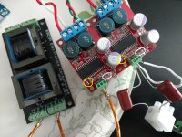
I attempted two simple mods: (1) replace the electrolytic power caps with OSCON; (2) replace the DC-blocking input caps with jumper wire. See the attached picture. The yellow circles are where I removed the factory caps and replaced with jumper wire.
As far as removing the input caps, my plan was to use an input transformer (Edcor TTPC15/15) for both DC blocking and unbalanced to balanced conversion.
It seems I managed to kill both boards.
In the picture, you can can see the left board is still connected to the transformer. I thought maybe the transformer itself was the problem, so I tried to re-create the capacitor setup on the right board: I jumpered - and GND intputs (white wire), then put caps (big brown guys) between + and - and an RCA jack.
When I powered up the board with the caps, the speaker attached to that board immediately pushed out all the way. No sound though. (Thank goodness for excursion limiters!)
When using the transformer, I get no sound at all, and no speaker movement.
The tda8932 boards do get warm though, so it appears they are getting power.
I used my DMM to check continuity between the input screw terminals and the actual tda8932 chip pins.
Any thoughts I what I did to break these boards? I did use almost the hottest setting on my soldering iron, the factory solder is miserable to work with. But I really don't think I overheated the boards, as I was holding them in my hands while doing most of the work. They get warmer in actual use than from my soldering. Those factory electrolytics were practically welded to the board.
Also, unrelated side question: what is the component circled in white? I'm guessing it's a diode? Any idea what it's function is?
Attachments
- Home
- Amplifiers
- Class D
- Fasten seat belts. TDA8932 pessimistic review.