If you're driving BTL loads, syncing two chips 90 degrees out of phase makes more sense doesn't it?
Got some free time again, time to finally get this heatsink thing figured out and finish my card.
Sent from my Nexus 4 using Tapatalk
The power being delivered to the load, ie the audio signal, is completely different to the square wave switching of the chip itself. As far as I am aware all four channels switch together and are synchronous to one common oscillator.
When you wire up a slave with reversed clock polarity it means that as one chips output stage (say the masters) is switching off the others (thee slave) is switching on. Meaning there is always one chip on and one off, rather than both on and both off at the same time.
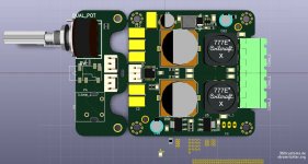
Work in progress, the "shrink mod".
Baseboard will be 60*60mm to fit in an enclosure, front panel will be an optional brake-away.
Nice! How do I order?
")
Cheers,
Mike
I used an lm46002 for its supposedly decent emi performance! Providing the layout is good.
Did you check them with a mobile phone?
Nice! How do I order?
Cheers,
Mike
Will let you know when i'm on the finish line.
It's actually a pretty tight fit.Did you check them with a mobile phone?
+1
How exactly are you supposed to check it with a mobile phone?
dial 1-800-EMI-HOME and see if it answers.
I heard of using small AM broadcast radio before, but this is the millennial (milleurista) solution in the makings*
everything is fine as long as their smart phone and Wi-fi isn't affected
Last edited:
Edit: The point is having your mobile coupling into the circuit rather than your switcher degrades phones performance.
no wonder you didn't laugh at my dial-800-joke, it was closer to the truth.
just so you know, in smarter phones( all of them) the PA RF transmit power is vastly reduced in good receive areas, so this "test" may give spotty results.
no wonder you didn't laugh at my dial-800-joke, it was closer to the truth.
just so you know, in smarter phones( all of them) the PA RF transmit power is vastly reduced in good receive areas, so this "test" may give spotty results.
Add the variety of frequencies, modulation schemes and signaling cadences and you are up to a quite some testing to cover what is out there...
//
Thing is, a BTL amp already has two channels operating 180 degrees out of phase. Assuming 50 percent duty cycle (zero volts DC output across the two outputs) and BTL outputs, one BTL leg (call this speaker +) will switch high while the other BTL leg for the same channel (call this speaker -) will switch low. Then halfway through the PWM cycle, they'll flip back.The power being delivered to the load, ie the audio signal, is completely different to the square wave switching of the chip itself. As far as I am aware all four channels switch together and are synchronous to one common oscillator.
When you wire up a slave with reversed clock polarity it means that as one chips output stage (say the masters) is switching off the others (thee slave) is switching on. Meaning there is always one chip on and one off, rather than both on and both off at the same time.
If you sync two of these BTL channels in phase, at the beginning of the PWM cycle speaker + on both channels will switch high together and speaker - on both channels will switch low together.
Now if you sync the two channels 180 degrees out of phase, speaker + on the "zero degree" channel will switch high at the same time as speaker - on the "180 degree" channel. Effectively you've got the same situation as if you simply renamed speaker +/- for the second channel, inverted the audio input, and did zero degree synchronization.
But if you sync the second channel 90 degrees out, the 2nd channel's switching events will lie halfway between the switching events of the 1st channel.
Of course all this assumes AD modulation (I haven't thought about how BD would work in this scenario, have to stare at some timing diagrams) and no audio signal present.
Guess, this will be a hot-rod. 
http://www.diyaudio.com/forums/attachment.php?attachmentid=518381&stc=1&d=1449540159
http://www.diyaudio.com/forums/attachment.php?attachmentid=518381&stc=1&d=1449540159
Attachments
Guess, this will be a hot-rod.
http://www.diyaudio.com/forums/attachment.php?attachmentid=518381&stc=1&d=1449540159
Your rendition looks amazing!!
Very nice doctor!
So there is no consensus about having the slave in phase or out of phase with the master clock? Given the BTL configuration there will be concurrent switching regardless of clock configuration so I don't think it makes a difference. The datasheet isn't very helpful in this regard.
So there is no consensus about having the slave in phase or out of phase with the master clock? Given the BTL configuration there will be concurrent switching regardless of clock configuration so I don't think it makes a difference. The datasheet isn't very helpful in this regard.
Nice hotrod Doctormord!!! It looks like it could fit in my shirt pocket, heatsink and all! Maybe even a pair of them! I'm a newbie but I want one like that.
I was planning on making up a few TPA3116 boards to tri-amp some speakers and subs so I've been reading both 3116 and 3251 threads, sponging up the knowledge each of you share. Its been enough to make me think I can do it too!
These 3251 chips are cool.... give me a lot more headroom on 2R loads should I need it in the future. If I can get Kicad figured out (struggling with first attempt of new library creation), I'm going to make a few 3251s too.
Wish TI would publish their *.bxl device files in a compatible format for easy import into Kicad... I'm struggling bad. Its fun though.
- Home
- Amplifiers
- Class D
- TPA3251d2