Doctormord and Gmad both have working examples of the 3251 and it would seem either one could add this external feedback circuit and let us know if it does improve the amplifier over the circuit without this added feedback loop.
If I understand this additional circuit correctly it will not only decrease the need for the as large an output inductor but it will also decrease some type of distortion and at the same time I think that this is lowering the output impedance of the circuit allowing for better matching to many real loudspeaker loads. Correct me if I have this wrong.
If I understand this additional circuit correctly it will not only decrease the need for the as large an output inductor but it will also decrease some type of distortion and at the same time I think that this is lowering the output impedance of the circuit allowing for better matching to many real loudspeaker loads. Correct me if I have this wrong.
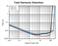
Plus it seems that the 3251 has ever so slightly lower distortion vs the 3255.
From the datasheets:
Attachments
Doctormord and Gmad both have working examples of the 3251 and it would seem either one could add this external feedback circuit and let us know if it does improve the amplifier over the circuit without this added feedback loop.
If I understand this additional circuit correctly it will not only decrease the need for the as large an output inductor but it will also decrease some type of distortion and at the same time I think that this is lowering the output impedance of the circuit allowing for better matching to many real loudspeaker loads. Correct me if I have this wrong.
Well they aren't the only ones with working examples
")
I've already modified my 6 channel PCB design to allow for pffb so we shall see.
The output filter inductor size absolutely needs to remain of decent value as the amplifiers stability with pffb is affected significantly by how the filters response affects the amplifiers frequency response, especially without a load connected.
Freedom from the load dependent frequency response is an additional benefit as well as the pffb helping to correct for inductor nonlinearities. I'm especially interested in the lowered noise too.
The tpa325x range is known for having rising 2nd order distortion as frequency decreases and it will be interesting to see if that is improved.
Thanks 5th Element for the comments. I would assume those tube aficionados would like the rising 2nd harmonic! So leave the inductor alone and just add this to the circuit. I have someone working on a design for me using this chip with an ADAU1701 along with a smaller 10 watt amplifier with the 3251 in at least Bridged mode if not parallel bridged mode and something in between to feed it a balanced output signal. There will be WiFi and if I get my way a USB input and a simple analog input.
Kindhornman,
I do not think that the reduction of the third harmonic below 0.003% will be noticeable to the ear. Conversely, you can raise the level of the second harmonic using a DSP.
That measured analog amplifier class A. This amplifier became my standard for sound quality.
I do not think that the reduction of the third harmonic below 0.003% will be noticeable to the ear. Conversely, you can raise the level of the second harmonic using a DSP.
That measured analog amplifier class A. This amplifier became my standard for sound quality.
Attachments
The odd order harmonics are dominant with these designs. This is because they are bridged/balanced and as a result the even order non linearities tend to cancel out.
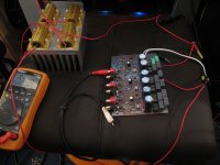
Gmarsh I am using an ASUS Xonar Essence ST soundcard ADC for the measurements. The signal source is a DAC based on the ESS 9018.
Gmarsh I am using an ASUS Xonar Essence ST soundcard ADC for the measurements. The signal source is a DAC based on the ESS 9018.
5th element thanks for that explanation. When someone is using the 3251 in four channel SE mode would the 2nd order still cancel or is that only in the bridged/ parallel modes?
The cancellation effects that occur will only happen when using the amplifiers in bridged mode.
Well I've now got the amplifiers back in their case and wired up to the proper power supply. (A picture of the old one can be found in this thread somewhere).
It is always more of a challenge to build a multichannel amplifier vs a stereo version. Circuit board complexities increase making routing harder and with circuits that deal with both low and high level signals this can result in some degradation in overall performance.
With my previous 6 channel design this was the case but only to a small degree. The overall level of 2nd order distortion was higher than it should otherwise be and instead of hitting a minimum of say 0.000x% it was sitting more around the 0.001-2% level. Nothing excessive, but compared to my implementations with the TPA3250 in combination with the PCM5242, I knew I could do better.
Of course the 6 channel amp uses single ended inputs and thus requires a degree of signal conditioning to feed the TPA3251s. The other implementations had the PCM5242 literally centimetres away from the 3251 and driving it balanced, so that could have also been a factor.
The old 6 channel vs new 6 channel had one slight difference besides the post filter feedback and that was how the RC filtering was applied. Previously I had a 3.3R resistor feeding each gate driver PSU pin. This is how the datasheet suggests you isolate the gate drivers from VDD, with VDD fed directly from the regulator.
The demo boards do it slightly differently though. They have the gate driver pins connected directly to the regulator with VDD then fed via a 3.3R resistor.
In my PCM5242 implementations I went with the second options as it's ever so slightly less complex (one 3.3R resistor vs two!). As this appeared to work really well I figured I'd duplicate that in the new 6 channel, post filter feedback, implementation.
Either way I have now measured all 6 channels and can say that this is a definite improvement vs the old one. It basically solved all the old issues, gives lower noise and a frequency response that's largely unaffected by the load impedance.
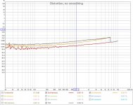
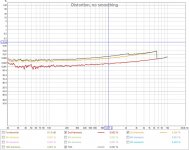
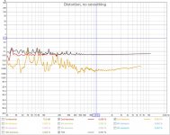
4 out of the 6 channels measure as the attached pictures show. Drive levels and the load connected are annotated.
The other 2 channels do show slightly higher levels of 2nd order but in this case it's only to a level of around 0.0008% instead of ~0.0002%.
Ignore the uneveness towards the lower frequencies as this is a result of some ground noise. And ignore the odd spikes here and there as that's an anomaly in the ASIO configuration that pops up every now and again.
It is always more of a challenge to build a multichannel amplifier vs a stereo version. Circuit board complexities increase making routing harder and with circuits that deal with both low and high level signals this can result in some degradation in overall performance.
With my previous 6 channel design this was the case but only to a small degree. The overall level of 2nd order distortion was higher than it should otherwise be and instead of hitting a minimum of say 0.000x% it was sitting more around the 0.001-2% level. Nothing excessive, but compared to my implementations with the TPA3250 in combination with the PCM5242, I knew I could do better.
Of course the 6 channel amp uses single ended inputs and thus requires a degree of signal conditioning to feed the TPA3251s. The other implementations had the PCM5242 literally centimetres away from the 3251 and driving it balanced, so that could have also been a factor.
The old 6 channel vs new 6 channel had one slight difference besides the post filter feedback and that was how the RC filtering was applied. Previously I had a 3.3R resistor feeding each gate driver PSU pin. This is how the datasheet suggests you isolate the gate drivers from VDD, with VDD fed directly from the regulator.
The demo boards do it slightly differently though. They have the gate driver pins connected directly to the regulator with VDD then fed via a 3.3R resistor.
In my PCM5242 implementations I went with the second options as it's ever so slightly less complex (one 3.3R resistor vs two!
). As this appeared to work really well I figured I'd duplicate that in the new 6 channel, post filter feedback, implementation.Either way I have now measured all 6 channels and can say that this is a definite improvement vs the old one. It basically solved all the old issues, gives lower noise and a frequency response that's largely unaffected by the load impedance.
4 out of the 6 channels measure as the attached pictures show. Drive levels and the load connected are annotated.
The other 2 channels do show slightly higher levels of 2nd order but in this case it's only to a level of around 0.0008% instead of ~0.0002%.
Ignore the uneveness towards the lower frequencies as this is a result of some ground noise. And ignore the odd spikes here and there as that's an anomaly in the ASIO configuration that pops up every now and again.
Attachments
Ah, okay. Then i did like in the datasheet. Thanks.
From your posting it appears/sounds like, the EVM solution is the better one compared to the datasheet version.
One resistor for all?
It would appear so.
Maybe the gate drivers perform better with a low impedance connection to the supply. Or perhaps putting the RC filter before VDD isolates it better from the noise that the gate drivers create.
Putting an RC to each gate driver should stop the noise getting out, as well as getting in, so should isolate VDD pretty well. But I'm guessing that putting the RC filter before VDD actually gives it better isolation.
- Home
- Amplifiers
- Class D
- TPA3251d2