I'll sell the card with a warning that if you're listening to full scale "tonecore" music, the inductors will get hot.Nah, 36V/3R is the real deal!
(I'm afraid to google that term, for all I know there's probably a genre of 'music' centered around different wave shapes/frequencies...)
If I am requesting a free sample it allows a back order, however with paid stuff that doesn't seem to happen.
Same here, samples are on backorder. Please send me a pm to shipping adress.
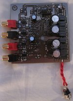
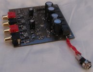
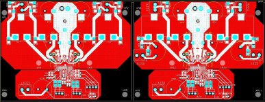
The pictures are not so great due to bad lighting, but they boards are now done.
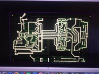
The only thing left to do is solder on the TPA3251 chips and the 1uF caps in the output filter. These are polypropylene and are quite large physically. I will put them on the underside of the board.
The board itself uses a LM46002 buck converter to step down the power stage voltage to a more appropriate level. This is then post regulated by a pair of LT3042s.
I had wanted to use these since Linear released them but haven't had a use for them yet. Well here I figured they would make good sense, what with their excellent high frequency PSRR for removing the grunge that the switcher could put out. I have actually measured the grunge that the switcher puts out with the scope and it is minimal to say the least.
One LT3042 feeds the TPAs and one feeds the opamps on the input stage. I am using LME49724 fully differential opamps for the input stage.
There is a micro controller included to control the power up sequence to ensure quite start up and to allow the unit to be trigger turned on and off by another unit.
I figured I'd add in decent quality parts just to see what the TPA is capable of. It's not exactly fair to do comparisons to my other amps with a design built on compromise as they were not.
Attachments
Do you expect this layout to be capable of running the chips at full power? Is this a 2oz. copper pcb? What about cooling? Nice one so far.
Are those really 4u7 MLCCs at rated voltage?
2oz yes, full power? Probably not. One of the applications intended for is the mid and treble section of an active setup, it's got good sensitivity too and I use hardly any power. The other would be another active setup this time two way with 8 ohm drivers. Again not particularly challenging in terms of current or dissipation. It will be interesting to see just how far the intended heatsinking will go.
Which caps are you referring to?
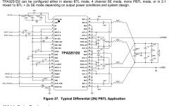
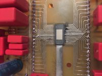
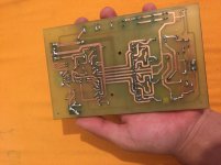
Hi, I am fairly new to electronics and i requested TI's TPA3251 a week ago. I received 5 of them yesterday and I just finished my PCB. I made a PBTL Version And It burned out just when gave the IC its juice. I couldn't see any solder bridges on my PCB so I can't figure out where the problem is, cause I followed TI's Schematic as my 1st Prototype. I didn't connect The Reset, Fault neither the OTW warning pins. I don't know if thats alright or not cause they say in the data sheet that those pins are only for resetting the chip and warning outputs, which I don't want to use for now. Elec caps are 35V and the red Film caps are all 63V ( Wima ) I have only used good brand stuff so I really can't figure out where the problem is btw The PCB has a thick solder mask on the SMD side so the traces are no problem besides I didn't connect a load... I'll attach the pics and I hope someone can help me
Ps. sorry for my bad english, hope I can improve
I'll attach the pics and I hope someone can help me Ps. sorry for my bad english, hope I can improve
Attachments
The linear regulators output caps.
Yup 4.7u 50V 1206s.
The linear regulators output caps.
Yup 4.7u 50V 1206s.
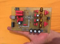
My first two versions.
DUG,
Looks good. Looking forward to see the final version.
Regards,
DUG,
Looks good. Looking forward to see the final version.
Regards,
Indeed an interesting alternative on the layout.
Indeed an interesting alternative on the layout.
can I put single end signal to A&B input , i use stereo BTL mode .
Thanks
can I put single end signal to A&B input , i use stereo BTL mode .
Thanks
No you cannot.
This is one of the disadvantages of this chip the channels work completely independently from one another.
When set into BTL mode the individual channels have their switching/modulation scheme modified accordingly to work in pairs, but besides that work completely independently from one another.
If you put the same single ended signal into both A and B then you will get nothing on the output as the two signals will cancel each other out perfectly, you need to invert one of them otherwise it will not work.
This is the reason why gmarsh and I have included fully differential opamps before the TPA3251. It is necessary if you want to use the amplifier with a single ended input. Doctormord's implementation uses a separate input pcb to much the same effect, but still single ended to balanced conversion is necessary.
Using an input buffer before the amplifier is a good idea anyway as it offers a degree of protection for the device. The inputs can only tolerate a certain amount of voltage swing and frying the chip is not a good idea.
using differential on any class D is a definite advantage ( RE common mode noise ), which is why I lose interest in most implementations. hence folks with input transformers or buffer boards are way ahead. but when not included on cheap amps aren't so cheap or easy anymore.
how bad is the common mode noise? basically really really bad and gets worse with more power out. This is the (dirty) secret of SMPS and class D
how bad is the common mode noise? basically really really bad and gets worse with more power out. This is the (dirty) secret of SMPS and class D
Last edited:
Indeed an interesting alternative on the layout.
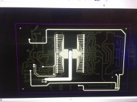
Yes, heavy on the power supply bypass and lighter on the output paths.
I will see if there is feedback on the output to inputs with the traces under the IC.
Experimentation, gotta love it.
? I don't use a seperate PCB, SE to Diff is already onboard.
Do you use a specific IC as SE to DIF or just invert the +input to get the -input?
- Home
- Amplifiers
- Class D
- TPA3251d2