All good points. The data sheet is unclear but by if efficiency is better than 90% at 2x100W then the ancillary circuits are taking about 20W. So you need to add that to the figure. So for 50w you need 70W PSU.
Regarding the components I totally agree, 25V cap across a supply rated up to 36V?
However as you say they are good fun.
Regarding the components I totally agree, 25V cap across a supply rated up to 36V?
However as you say they are good fun.
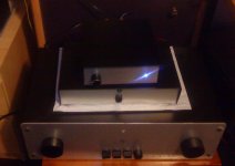
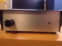
I just finished one of these cheap ebay TDA 7498 Amps.
I use a 36V 200W switching power supply to power it up, which I run at 31V.
I have tested it in two different set of speakers. What is noticeable is there is a lot of bass. Especially in a, 8 ohm Celeph speaker set.
In a pair of normal everyday Aiwa 6 ohm set it seems to promote a little bit more mid and high frequencies but still there are plenty and very good low’s.
It is dead silent with no input signal, even though its input gain is set a little bit high.
In it pros is that it comes with 63V filter caps, and through hole, not smd caps at the output filter. It also has a 12V voltage output on the board for a fan or whatever someone might think to hook up.
Drawbacks are that its audio input caps are smd type (as everything else) so it is not easily tweaked.
I am amazed from the detail and bass this small amp has. It performs extremely well for its price.
And there is no hum or other noises generated from the board or from the SMPS injected into the amp.
Attachments
@drunktnk,
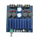
I have the same board and like it. Can you confirm that on board PSU is 12 V? According to the schematic in the data sheet, it is 3.3V.
If you look closely to the 2nd picture attached "J7" is marked Vout. That is trim-able by the trimmer next to the heatsink, on the right hand side, and currently I 've got it at 11.5V powering a led with a resistor in series.
Next to it (J7) there are (J4, J6) the mute and the standby output sockets, these (J4, J6) are at 3.3V, between pin and ground, as per schematic.
Interesting. I did not realise that. Look like this is something extra since I did not see any 12 V supply on the schematic (see attached). Thanks!
Attachments
Interesting. I did not realise that. Look like this is something extra since I did not see any 12 V supply on the schematic (see attached). Thanks!
Yes, this is the schematic provided by manufacturer of the chip, as a guide for implementation. Usually all these cheap board amps from China use these schematics as board layouts (no R&D on their own). But sometimes they put something extra. Probably that is with this board.
There is also an application note from ST with more details about layout etc. if you like some more info.
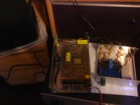
I bought one of these boards the other day.
Sadly I bought the Wrong board, the one with the big white resistors on. If you bought this board too, know also that you have bought the wrong board.
Apart from the tiny, hopelessly wrong value inductors on the board, the unhelpful black colour and lack of access to mute and standby, the reason no one gets any bass from this board is simple. The designer has routed all of your audio through 5W 2.2R resistors. Quite how 100W is supposed to travel through those is unclear, especially into a 4ohm load.
I have no idea why he did that, just that if you have a choice, never buy this board, it's rubbish.
image sharing sites
As I did accidentally buy it, and I know this chip can sound very nice I decided to do a few mods, although I haven't switched it on since the mods so it's all still rather unproven, and I still may buy a better board and move my stuff over.
So, what needs changing?
1) Strip off ALL filter components and those idiotic 2.2R resistors.
2) Replace the inductors with 10uH ones of sufficient size.
3) Use 220n caps as per Trevor Marshall's page, the 22R-220nF pair can be easily mounted under the board.
4) Find the 39K resistor that sets it to 310kHz. I have no idea why it's there, it needs to be 33K so you get 351kHz, so either change it or bridge it with a 220k, watching for heatsink clearance (I tipped mine over - 2.5mm holes and screw right in.).
5) Find the hopeless input capacitors and whip them off with a big hot soldering iron. Replace them with something sane.
6) I also replaced the main cap for a known good one I had out of a decent SMPS of 3,300uF, 50V. Oscons would also be good but only up to 25V...
I haven't looked at the mute etc yes, it's all tiny black tracks, you really want to reduce the gain (ground Gain0 and Gain1 pins) and put an anti pop thing onto the mute, or use a delay relay for your speakers. The pop is caused by the input cap (replaced in 5) charging up IIRC, so setting no volume when you switch on should help.
This chip CAN sound excellent as my much modded Muse S7 now sounds very sweet indeed, but you have to mod them. The board with the mute socket looks great and will probably need far less work!
Detail of the replacement for the 5W 2.2R - I used 1mm copper as I had some around:
pic upload
(edit - made pictures bigger)
Sadly I bought the Wrong board, the one with the big white resistors on. If you bought this board too, know also that you have bought the wrong board.
Apart from the tiny, hopelessly wrong value inductors on the board, the unhelpful black colour and lack of access to mute and standby, the reason no one gets any bass from this board is simple. The designer has routed all of your audio through 5W 2.2R resistors. Quite how 100W is supposed to travel through those is unclear, especially into a 4ohm load.
I have no idea why he did that, just that if you have a choice, never buy this board, it's rubbish.
An externally hosted image should be here but it was not working when we last tested it.
An externally hosted image should be here but it was not working when we last tested it.
image sharing sites
As I did accidentally buy it, and I know this chip can sound very nice I decided to do a few mods, although I haven't switched it on since the mods so it's all still rather unproven, and I still may buy a better board and move my stuff over.
So, what needs changing?
1) Strip off ALL filter components and those idiotic 2.2R resistors.
2) Replace the inductors with 10uH ones of sufficient size.
3) Use 220n caps as per Trevor Marshall's page, the 22R-220nF pair can be easily mounted under the board.
4) Find the 39K resistor that sets it to 310kHz. I have no idea why it's there, it needs to be 33K so you get 351kHz, so either change it or bridge it with a 220k, watching for heatsink clearance (I tipped mine over - 2.5mm holes and screw right in.).
5) Find the hopeless input capacitors and whip them off with a big hot soldering iron. Replace them with something sane.
6) I also replaced the main cap for a known good one I had out of a decent SMPS of 3,300uF, 50V. Oscons would also be good but only up to 25V...
I haven't looked at the mute etc yes, it's all tiny black tracks, you really want to reduce the gain (ground Gain0 and Gain1 pins) and put an anti pop thing onto the mute, or use a delay relay for your speakers. The pop is caused by the input cap (replaced in 5) charging up IIRC, so setting no volume when you switch on should help.
This chip CAN sound excellent as my much modded Muse S7 now sounds very sweet indeed, but you have to mod them. The board with the mute socket looks great and will probably need far less work!
Detail of the replacement for the 5W 2.2R - I used 1mm copper as I had some around:
An externally hosted image should be here but it was not working when we last tested it.
pic upload
(edit - made pictures bigger)
Last edited:
..And another thing for owners of this board, the speakers will be out of phase if you follow the white lettering. In reality (from the datasheet and listening tests) both the +ve connections are on the outer edge of the board. I did wonder why my proper filter still gave no bass LOL.
I adjusted my symbols with a black marker pen and tippex.
images upload
Also - don't run this board on 20V as it refused to even start for me. I thought I'd killed it but kept not finding anything wrong, so I abandoned that PSU (my old Topping 20V) and pushed the full 32V, 200W up it and it worked just fine.
My inductors sound nice too, the sound is really coming together now and it does a good square wave (tested at 440Hz into an 11ohm load at up to about 15W.
The board is now clocking at 358kHz with the 220k bridging the 39k clock resistor, which is nice. Still very crisp on/off transitions from all 4 chip outputs.
No heat issues at 32V either, everything is nice and 'not quite cold'.
Next mods are bulk capacitances.
I adjusted my symbols with a black marker pen and tippex.
An externally hosted image should be here but it was not working when we last tested it.
images upload
Also - don't run this board on 20V as it refused to even start for me. I thought I'd killed it but kept not finding anything wrong, so I abandoned that PSU (my old Topping 20V) and pushed the full 32V, 200W up it and it worked just fine.
My inductors sound nice too, the sound is really coming together now and it does a good square wave (tested at 440Hz into an 11ohm load at up to about 15W.
The board is now clocking at 358kHz with the 220k bridging the 39k clock resistor, which is nice. Still very crisp on/off transitions from all 4 chip outputs.
No heat issues at 32V either, everything is nice and 'not quite cold'.
Next mods are bulk capacitances.
Nice mods Globulator. I think I have the same board and agree the speaker labels are bass ackwards. ") however I have no issues with it sounding great totally stock. Works with 19v SMPS even. I am currently using 24v and driving it with outs from miniDSP and my 2 way active speakers make lots of bass the response measures flat and speaker impulse response is clean. I wondered about the big 2.2ohm power resistor too but think it won't harm anything as emitter resistors are common in discrete solid state amps and they are used to provide some damping to prevent oscillation. So these may actually part of the overall RF snubber circuit. You may be letting RF emissions through (speakers won't hear it but they might be dissipating in the VC's).
however I have no issues with it sounding great totally stock. Works with 19v SMPS even. I am currently using 24v and driving it with outs from miniDSP and my 2 way active speakers make lots of bass the response measures flat and speaker impulse response is clean. I wondered about the big 2.2ohm power resistor too but think it won't harm anything as emitter resistors are common in discrete solid state amps and they are used to provide some damping to prevent oscillation. So these may actually part of the overall RF snubber circuit. You may be letting RF emissions through (speakers won't hear it but they might be dissipating in the VC's).
however I have no issues with it sounding great totally stock. Works with 19v SMPS even. I am currently using 24v and driving it with outs from miniDSP and my 2 way active speakers make lots of bass the response measures flat and speaker impulse response is clean. I wondered about the big 2.2ohm power resistor too but think it won't harm anything as emitter resistors are common in discrete solid state amps and they are used to provide some damping to prevent oscillation. So these may actually part of the overall RF snubber circuit. You may be letting RF emissions through (speakers won't hear it but they might be dissipating in the VC's).Nice one - so all this uber-mods but keeping the dc-barreljack?
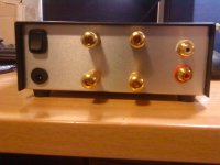
Good spot Doctormod. What is the current rating of those connectors?
Nice mods Globulator. I think I have the same board and agree the speaker labels are bass ackwards.
Ah yes - I remember now, you recommended this so I bought it
. It was quite cheap though. Very cheap in fact....I think you have a synergy with your speakers that I don't have, but I also think that phase inversion made me think it was far worse than it was. A earlier post in this thread also complains of no bass - probably for the same reason
As for the 2.2R, nice theory - probably true in parts too. However a transistor amp will use smaller ones like 0.22R, which are there for thermal stability: MOSFETs with a PTC don't need them at all. They'll also be wrapped in GNFB and as they are linear, therefore become invisible..
Also 2.2R with 100W into 4 ohm will dissipate about 35W and give a damping factor of < 1.8, into 8ohm you get rid of 22W and a damping factor of < 3.6 so that's much better LOL
. I'm using Trevor Marshall's filter design which he demonstrates on a TDA7498 so I'm confident of good filtering, also my scope confirms that there isn't much coming out and what is there is largely sinusoidal.
The main thing for me is it's a cheap good fun amp, I still marvel at the welly that comes out of something smaller than the nail on my smallest finger, and it takes all the abuse I give it and Keeps On Trucking, quite unlike my TK2050 I destroyed earlier
Good spot Doctormod. What is the current rating of those connectors?
.Nothing gets soldered until I stop taking it in and out, I'm not sure when that'll be though - the curse of DIY is that you always think of something new to try and tinker with...
the 330p/22r snubbers are on topside board in your photo, you decided to add another pair on bottomside as well ? Why ?
Good question.
The topside snubbers snub across between both outputs, whereas the ones I added (330pF 10ohm) snub both outputs to ground.
I could remove the factory ones now I guess but looking at the scope it doesn't seem to do much harm, and bing SMD they will be tighter than mine.
Mind you I'm not sure mine do much either, although they will work depending upon the amount of PWM movement. The scope was happy, very little overshoot now. Still some mind.
Also you have to factor in that I ordered about 50 of these little 330pF so I'm going to use them now
Last edited:
I wouldn't trust them at more than 2.5-3A, cheap Chinese one even less."SWC" brand ones are rated up to 5A, but always keep contact resistance in mind.
I agree, I should solder on a little green screw connector there. I have some too that I bought for the tiny 3118 PBTL boards... a future mod.
What really surprised me was how well it worked when I left such long leads on those 220nF caps, I seem to be useless at re-using through holes so I just solder through hole components straight on the top like SMD. Sometimes I need to dab on a little flux to help as tin is awful when the flux leaves, but that means those caps are around 10mm off the board!
Well, this could crack/break the MLCCs termination which can't easily be seen and is prone to a long-term defect. Think about what would happen if they short.
Oh! What is the crack mechanism? (The are not under any strain!).
Nice to avoid a short - I've £5.16 invested in this amp.
- Status
- Not open for further replies.
- Home
- Amplifiers
- Class D
- Ebay cheap TDA7498 boards