Member
Joined 2009
Paid Member
I don't know much about Class D other than the basic principles, so I'm mostly ignorant about current 'chips' and advances.
I'd like to know how Class D amplifiers compare with, say, Class A amplifiers, in terms of total phase delay through the amplifier - are they better or worse or about the same. About the same is just fine but I had been under the impression that the filter needed on the output of a Class D amplifier produced unwelcome phase delays and that they might be speaker dependent too. So recently I came across these 'spread spectrum' options for Class D amplifiers which are 'filterless' - I assume it means they radiate all over the place but in such a way that it isn't objectionable or is this technology restricted to boom-boxes with short speaker cables ??
So without any output filters, do these 'filterless' amplifiers have good phase response over audio range ???
The filter bank on a properly designed class D amp, even though it has an inductor and capacitors in the output path between the IC and the speaker, should not affect the phase of the audio signal too much. The phase altering effects of the speaker itself, or cross-over, or the room reflections are much more significant. The inductor and capacitor together form a high pass circuit designed to heavily attenuate the switching frequency.
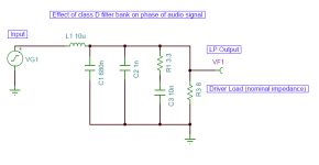
Take for example the Texas Instruments TPA3116D2, the current class-D wunderamp: it has a 10 uH coil coupled with a 680 nF capacitor low pass filter. It also has a 1 nF cap directly tied to ground plus a 3.3 ohm R and 10 nF cap in series which then tie the output to ground for an RF/EMI filter.
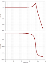
If you look at the AC transfer characteristics of these items in a circuit simulator program (TINA for example, a nice fully featured free SPICE program from TI), you can see the amplitude and phase that these coils and caps induce on the AC signal going from the amp to the speaker.
Here I have a circuit representing the signal path from the amp IC output through the recommended filter and driving an 8 ohm speaker.
The resulting transfer function is pretty flat but has a +1dB gain at 20 kHz and -10 deg phase angle at 20 kHz, and otherwise flat. The filter is designed to block the 400 kHz or higher switching signal. The attenuation is -34dB at 400 kHz.
So unless you are worried about a 10 deg phase difference at 20 kHz, I would say that the class D topology is actually very phase linear. Running without the coil is not going to buy you much other than spraying the world with unintended RF noise.")
Take for example the Texas Instruments TPA3116D2, the current class-D wunderamp: it has a 10 uH coil coupled with a 680 nF capacitor low pass filter. It also has a 1 nF cap directly tied to ground plus a 3.3 ohm R and 10 nF cap in series which then tie the output to ground for an RF/EMI filter.
If you look at the AC transfer characteristics of these items in a circuit simulator program (TINA for example, a nice fully featured free SPICE program from TI), you can see the amplitude and phase that these coils and caps induce on the AC signal going from the amp to the speaker.
Here I have a circuit representing the signal path from the amp IC output through the recommended filter and driving an 8 ohm speaker.
The resulting transfer function is pretty flat but has a +1dB gain at 20 kHz and -10 deg phase angle at 20 kHz, and otherwise flat. The filter is designed to block the 400 kHz or higher switching signal. The attenuation is -34dB at 400 kHz.
So unless you are worried about a 10 deg phase difference at 20 kHz, I would say that the class D topology is actually very phase linear. Running without the coil is not going to buy you much other than spraying the world with unintended RF noise.
Attachments
Member
Joined 2009
Paid Member
Running without the coil is not going to buy you much other than spraying the world with unintended RF noise.
Filterless = approx 80% reduction in IMD. There's a good TI white paper on this.
Cheers,
Mike
Filterless Class D gets around EMC regulations by spreading more RF muck over a much bigger area, so each piece of land gets a thinner layer of muck. Personally, I would ban them by rewriting the EMC regulations to have a lower threshold for wideband noise transmitters. Before too long the HF and VHF spectrum will become unusable in most towns and cities - there are already concerns about the effect on aircraft comms when overflying them!
I don't know much about Class D other than the basic principles, so I'm mostly ignorant about current 'chips' and advances.
I'd like to know how Class D amplifiers compare with, say, Class A amplifiers, in terms of total phase delay through the amplifier - are they better or worse or about the same. About the same is just fine but I had been under the impression that the filter needed on the output of a Class D amplifier produced unwelcome phase delays and that they might be speaker dependent too. So recently I came across these 'spread spectrum' options for Class D amplifiers which are 'filterless' - I assume it means they radiate all over the place but in such a way that it isn't objectionable or is this technology restricted to boom-boxes with short speaker cables ??
So without any output filters, do these 'filterless' amplifiers have good phase response over audio range ???
Any delay won't be audible as long it's linear and constant and not distorted over the audible band ( in theory
) as long as the original signal is not present ( in real time ) in the amplified signal . An example is a high quality audio signal transmitted by Bluetooth . The receiver receives the signal delayed , but there's little or no distortion , The delay will be visible if you use a Bluetooth wireless headphone on your TV
But the sound quality is as good . Cheers ,
Rens
Not really on topic , just a teaser
but it makes sense ?Take for example the Texas Instruments TPA3116D2, the current class-D wunderamp: it has a 10 uH coil coupled with a 680 nF capacitor low pass filter. It also has a 1 nF cap directly tied to ground plus a 3.3 ohm R and 10 nF cap in series which then tie the output to ground for an RF/EMI filter.
Filters should not be considered without load-impedance. Performance of filter is a function of frequency as the (real) loads impedance/parasitics will change with frequency as well.
Filters should not be considered without load-impedance. Performance of filter is a function of frequency as the (real) loads impedance/parasitics will change with frequency as well.
Yes, I thought of this, but I am not sure if I can put in a real dynamic driver impedance simulator into a SPICE circuit? I suppose adding at least Le of drive make some difference but really best way is to measure electrical phase in the actual system with a woofer tester or the like.
A ham operator I know, in his 70's and in the hobby for decades, laments the days when the HF spectrum wasn't full of crap and you could pull in people from all over the world with a cheap radio. Personally I find I can't pick up AM radio anymore - I can pick it up clear as day on the HF rig with my outdoor antenna, but on a consumer radio it's unlistenable because of the crap everything puts out now. I refuse to design anything filterless, because there's enough crap ******* over the RF spectrum as it is, and the world certainly doesn't need more.Filterless Class D gets around EMC regulations by spreading more RF muck over a much bigger area, so each piece of land gets a thinner layer of muck. Personally, I would ban them by rewriting the EMC regulations to have a lower threshold for wideband noise transmitters. Before too long the HF and VHF spectrum will become unusable in most towns and cities - there are already concerns about the effect on aircraft comms when overflying them!
If audiophilia is the goal, make your class D amp run at a higher switching frequency and up the output LC corner frequency to minimize the peaking/phase shift. Or use a UcD topology which puts the output LC in the loop - set the LC and feedback for a higher switching frequency if you really insist on chasing numbers. You'll need smaller FETs that can switch faster and/or beefier gate drive, and you'll have more switching/conduction loss which will make the amp less efficient, but you'll get closer to the "flat to whatever hz" that you're chasing.
Just don't be an ******* and make a mess of the spectrum just because you want your amp to have that extra 'sparkle' or whatever.
I just bought a Tang Band woofer (Tang Band W6-789E 6-1/2" Woofer) and Thiele-Small parameters were provided. About half way down this page (http://www.integracoustics.com/MUG/MUG/articles/woofer/) shows how to get some driver model parameters from the Thiele-Small parameters. I don't yet know how to get the speaker inductance based on those values, but it might be a start.
Yes, I thought of this, but I am not sure if I can put in a real dynamic driver impedance simulator into a SPICE circuit? I suppose adding at least Le of drive make some difference but really best way is to measure electrical phase in the actual system with a woofer tester or the like.
You may want to have a look into this:
Subwoofer design
and this
http://www.northreadingeng.com/Loud_equal_circuit.html
Just don't be an ******* and make a mess of the spectrum just because you want your amp to have that extra 'sparkle' or whatever.
Well, if the cables are quite short (10-20cm), it is IMHO valid to run an amp filterless. -> active loudspeaker
Last edited:
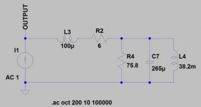
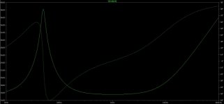
This is what my speaker model looks like based on the Thiele-Small parameters and a guess at the coil inductance. In retrospect, the coil inductance may be a bit low. It was chosen to give a 3db increase in the impedance at 10 kHz which is the upper end of the speaker frequency range. I used a one amp current source for the AC signal. At least it shows a (mechanical) resonance at 50 Hz as per the specs.
Attachments
Last edited:
A 20cm cable can make a fairly effective antenna at VHF/UHF frequencies, and the fast slews coming out of an unfiltered class D amp have content that extends well into the VHF band. Plus there's the whole "big coil of wire in a metal framed speaker" thing to deal with.Well, if the cables are quite short (10-20cm), it is IMHO valid to run an amp filterless. -> active loudspeaker
Unless you've got the appropriate equipment for EMI verification of a filterless design, don't build one.
Hell, just move the output LC frequency way up so it has very little effect in the audio band. Sure, the fundamental switching waveform might make it to your speaker without much attenuation, but at least you'll take a good dent out of any radiated EMI. Plus, using lower value inductors means you can select ones with a saturation current well beyond what'll go through them, improving IMD.
Regarding the EMI considerations, please look here for a test of my MAX9709 board:
http://www.diyaudio.com/forums/class-d/72237-max9709-5.html#post4017706
Regards,
Christian
http://www.diyaudio.com/forums/class-d/72237-max9709-5.html#post4017706
Regards,
Christian
A well designed LC filter, coupled with the speaker lumped T/S elements essentially has negligible phase delay. The TPA3116D2 expample is shown here in circuit sim with TINA spice program.
http://www.diyaudio.com/forums/class-d/237086-tpa3116d2-amp-448.html#post4029514
http://www.diyaudio.com/forums/class-d/237086-tpa3116d2-amp-448.html#post4029514
- Status
- This old topic is closed. If you want to reopen this topic, contact a moderator using the "Report Post" button.
- Home
- Amplifiers
- Class D
- low phase delay through filterless Class D?