Is this a four layer board, or two layer board?
Find it difficult to see (or did I missed something in all the posts??)
Otherwise I would highly recommend a 4-layer board.
It's not that much more expensive nowadays anymore.
By default I always use ferrite in the power lines, like a CLC filter (were L = ferrite)
This is also what you typically see in professional equipment.
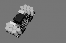
I managed to squeeze a 1kW about around the IRS2092 on a 50x100mm board, with the IRFP4227. With all caps, connectors and the inductor on top, all SMD parts on the bottom. 4-layer board, ground layer second layer (underneath the top layer)
The two MOSFETs also on the bottom, which can be mounted to an aluminum plate and/or the chassis for easy mounting.
Worked very nice, with very low noise and EMI.
Although, I think I would go for something else nowadays.
There were some restriction and compromises I had to make for the customer/client.
The IPP120N20NFD is also a good alternative with a lower Rds(on)
I made a little sheet here with interesting MOSFETs btw, feel free to update and re-upload.
Find it difficult to see (or did I missed something in all the posts??)
Otherwise I would highly recommend a 4-layer board.
It's not that much more expensive nowadays anymore.
By default I always use ferrite in the power lines, like a CLC filter (were L = ferrite)
This is also what you typically see in professional equipment.
I managed to squeeze a 1kW about around the IRS2092 on a 50x100mm board, with the IRFP4227. With all caps, connectors and the inductor on top, all SMD parts on the bottom. 4-layer board, ground layer second layer (underneath the top layer)
The two MOSFETs also on the bottom, which can be mounted to an aluminum plate and/or the chassis for easy mounting.
Worked very nice, with very low noise and EMI.
Although, I think I would go for something else nowadays.
There were some restriction and compromises I had to make for the customer/client.
The IPP120N20NFD is also a good alternative with a lower Rds(on)
I made a little sheet here with interesting MOSFETs btw, feel free to update and re-upload.
Attachments
I think the essence is well represented in last PCB drawing posted.
The ground going to the TO-220 on top of heatsink can be prolonged and swapped to top side, to get a ground plane for input section. The V- plane can be terminated when it is no longer needed, for example under gate driver IC. Currents travelling the path from V- grounded circuits to GND referenced circuits would essentially be the low current pulses used by gate driver IC for toggling latches, brief <100ns miliampere pulses.
A cut can be made in ground trace, starting under lower inductor pad and prolonging down for some length, so that the HF voltage drop in ground trace joining +V and -V capacitors does not cause common-mode ripple in the ground reference taken for input section. In other words, it's enough to take a clean reference from output section and convert it into ground plane in another place.
I don't recommend TO-247 for high speed switching because drain lead inductance is about 13nH, vs. about 6nH for a TO-220 mounted sandwiched between PCB with ground plane and heatsink with 6mm lead length before bend (the ground plane results in some reduction w.r.t. the 7.5nH quoted in datasheets). Maximum turn-off speed attainable with 13nH without a negative voltage for gate drive or inductor tricks is 1us*5V/13nH=384A/us. 5V is typ. average Vgs-th. In practice it is slower because gate has some internal resistance, and turn-off circuit has also some series resistance. For TO-220 it becomes 1us*5V/6nH=833A/us. Safe reverse recovery di/dt for 150V~250V body diodes is in the range from 400A/us to 800A/us. Turn off typically can be somewhat faster than body diode recovery/turn on, as long as supported by layout. Essentially current is toggling very fast from V+ to V-, so the big decoupling cap between V+ and V- near the FETs allows fast turn off, better with ferrite beads/pi filters in the rails to isolate the hash from the wiring.
Two layers and some SMD is just enough to make respectable single channel class D. Only for integrating more channels and PSU I recommend more layers.
Last edited:
In theory maybe, but if a client/customer want some specific measures, connectors or a certain type of mounting, that's definitely not always the case.Two layers and some SMD is just enough to make respectable single channel class D. Only for integrating more channels and PSU I recommend more layers.
In this case, there was absolutely no way to pull it off with two layers.
Simply because it was practically impossible.
Ideally I what have put the ground layer on top, but in this case I am using a SMD inductor, simply because a through hole wouldn't fit because how dense the bottom layer is with components.
For that reason a ground layer on top wouldn't really fit.
Keep in mind that this was with ±75-90V power rails, so you do want to keep some clearance here and there.
One thing I discovered, is that it's very important to decouple the power rails directly to the chassis (connected via M3 vias) and make sure how your ground wire (from the ground plane) is going back to the power supply.
And of course the standard separation between signal ground and power ground (which really can screw up your PCB design sometimes)
Unless you really need to turn every penny I also don't see why you wouldn't go for 4 -layer to be very honest.
Gives you so much more control and freedom.
I guess that's just a personal reference.
But ones again, there is no holy grail.
It all depends on the context and which compromises need to be made.
Most high power amplifiers from well known brands, that I have seen, all have 4-layers (or even more)
D109
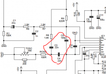
There was a PM regarding the indicator LED on the gain board.
D109 is the indicator LED of the limiter. It is not needed for the limiter functionality, but for indication only. This diode has to be a type with Vf=1.7V and high brightness. Types with Vf=2.1V will not light up. In order to drive any type of LED you would need one more NPN and one more resistor....
Regarding PCBs for class D, double sided with some SMD (and vias doable with solder and wire) has the particularity that it is the highest complexity that can be both etched and stuffed at a modest home lab, or ordered to a board house and PCB stuff factory. This is the bridge between DIY and professional. There shall be such a bridge.
I detect some lack of objectivity in the xls file found in MOSFET.zip. Some good FETs are chosen TO-247 so price increases while switching performance decreases. IRFB4615 and some others are missing. It should be noted that FDP2572 Rds-on and Qrr are specified for Id=9A while for IRFB4615 it's at 21A. FET selection precise to a deepest level requires some homogenization of data.
I detect some lack of objectivity in the xls file found in MOSFET.zip. Some good FETs are chosen TO-247 so price increases while switching performance decreases. IRFB4615 and some others are missing. It should be noted that FDP2572 Rds-on and Qrr are specified for Id=9A while for IRFB4615 it's at 21A. FET selection precise to a deepest level requires some homogenization of data.
Last edited:
Feel free to modify and update the xls file and re-upload it!!
I am definitely not saying it's perfect (far from even), I just started something as a quick reference.
But like you mentioned, it's sometimes difficult to compare because manufactures are not always giving the right amount of data.
There is always place for improvement!
edit:
I also just realized that this is the older version.
I lost my new version, I remember that it also had date of release/production in it.
(which can be a key issue for professional development)
Last edited:
D
Deleted member 148505
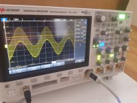
I listened to the sound of my implementation, problem is I prefer the sound of pre-filter feedback.
Also the oscillation doesn't start when there is no load and there's music signal on the input. (the relay does not engage). Workaround is to put a relay on the input signal which is controlled by timer.
Also the oscillation doesn't start when there is no load and there's music signal on the input. (the relay does not engage). Workaround is to put a relay on the input signal which is controlled by timer.
Attachments
....the relay does not engage). Workaround is to put a relay on the input signal which is controlled by timer.
Alternatively we could together try to understand why the relay does not engage and get your relay on the right track.
However for this you would need to disclose the full circuit details of your modifications and of your relay and protection circuit.
D
Deleted member 148505
Alternatively we could together try to understand why the relay does not engage and get your relay on the right track.
However for this you would need to disclose the full circuit details of your modifications and of your relay and protection circuit.
Hi Choco,
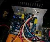
The amp is now ok, startup was fixed, just replaced values same on the attached schem, sound is many times better now, I like the sound of guitar, piano and sax.
Regards,
Lester
Attachments
Hi.
Can someone please recommend a commercial SMPS for this project (not hypex they too expensive for me)
OR..Can we start looking at developing an open SMPS for next year 2018, I feel there was good moment on this projec,t but to complete it, we need a power supply project to compliment the work, im stuck with heavy expensive transformer options which I cannot afford. How about a +/- 52v 8A model?
I have access for a small R&D budget and new epcos N87 cores and various some filter parts for the input for a offline SMPS, my issue is the magnetics and winding I will need help when the time comes for now its up for discussion.
Hi.
Can someone please recommend a commercial SMPS for this project (not hypex they too expensive for me)
OR..Can we start looking at developing an open SMPS for next year 2018, I feel there was good moment on this projec,t but to complete it, we need a power supply project to compliment the work, im stuck with heavy expensive transformer options which I cannot afford. How about a +/- 52v 8A model?
I have access for a small R&D budget and new epcos N87 cores and various some filter parts for the input for a offline SMPS, my issue is the magnetics and winding I will need help when the time comes for now its up for discussion.
hi reactance try any of the below and look also in that forum ,many affordable smps posted
Offline full-bridge SMPS....need help
Offline full-bridge SMPS....need help
Offline full-bridge SMPS....need help
Offline full-bridge SMPS....need help
if you want simple and cheap, have fun

hi reactance try any of the below and look also in that forum ,many affordable smps posted
Offline full-bridge SMPS....need help
Offline full-bridge SMPS....need help
Offline full-bridge SMPS....need help
Offline full-bridge SMPS....need help
if you want simple and cheap, have fun
Thank You stewin!
DIP version IRS2092 has been discontinued, and non-automotive grade SOIC IRS2092S is discontinued too, but SOIC AUIRS2092S is active (automotive grade). For SOIC to DIP there are adapters, but ordering from China can take over a month and trimming the traces not used may be a good idea, since one side is usually SOIC and the other TSSOP:
soic to dip 16 adapter | eBay
soic to dip 16 adapter | eBay
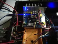
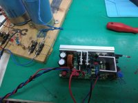
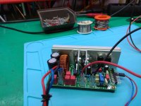
First board complete and tested with 2x55 V DC (its a 80V version) because I do not have +-80V power supply yet. It play music without buzz or noise,but I will do more tests when I make +-80V power supply.
Regards
zoky2
Regards
zoky2
Attachments
Good point. Ebay is not always my favorite for electronic components, but I think for adapters its perfectly fine. Thanks for showing this option.
Enjoy. In case of questions - simply post here.First board complete and tested...
First board complete and tested with 2x55 V DC (its a 80V version) because I do not have +-80V power supply yet. It play music without buzz or noise,but I will do more tests when I make +-80V power supply.
Regards
zoky2
nice work! what post have you used for the 80V version ?
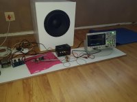
Iv'e completed my second 40V lite amplifier today, after almost a year in my draw the beast was unleashed today. Its been married to a Peerless 835017 12" driver the same driver SVS uses for their PB 2000 sub-woofer vie also used the same box volume to achieve the same response. And I did it
This tiny amplifier is incredible! I used a linkwitz transformer instead of the gain amplifier on the front-end, the results were more than satisfying!. My living room felt like a jet engine was above it windows was shaking and the bass was perceivable down to 19.5Hz, the energy of this amplifier is amazing, it will mostly be used for home theatre and occasional moderate load music.
I'm looking at designing a more mechanical friendly layout for the 65V version and replacing this 40V version.
Thus far the sound is just outstanding! enough bass to get the neighbors to call the cops!
Attachments
Last edited:
- Home
- Amplifiers
- Class D
- SystemD LiteAmp