"Feedback" in an IRS2092 is hardly "limited", since it is the difference signal that drives the amp.
The forward gain of a comparator PWM modulator is given by the ratio of the rail to rail supply voltage divided by the peak to peak voltage of the carrier at the comparator input. If you measure the carrier at Pin 4 of the IRS2092 of an LD25 when running with +/- 62V you will find a carrier with slightly more than 1Vpp.
Means the forward gain from comparator to switching node is around factor 120. Well, defined and limited. In front of the comparator you have an OTA gain stage with limited gain. And the external caps are beating down the gain towards high frequencies. Again well defined and limited. Together with the feedback you get a well defined and limited loop gain, which is massively droping over frequency.
Most of the 'bad things' do not happen at 400kHz. They happen with the high order harmonics contained in the 400kHz rectangles, means in the multi MHz range and higher. And the traces of the layout also do not matter because of the fundamental of 400kHz, but because of the extremely fast sloping of the rectangles and because of the required extremely fast current commutation events, typically between 200A/us...1000A/us. Take these numbers and assume 0.5nH trace inductance per mm length (just a rule of thumb, in fact the nH per mm depend on the track width and the geometric position of the backwards path ==> enclosed loop area). Then apply v = L*di/dt and you will notice that your tracks are not just tracks, but serious inductors. Then look at the caps at your rails and the parasitic capacitances of the MosFets ==> you will find tons of parasitic resonators formed the capacitances and the few nH from the tracks. The unpleasant modes of these resonators are in the range between 20MHz and 100MHz. This is where your 'bad things' really happen and most DIYers simply do not see them, because they are lacking the knowledge where to measure and often do not have a fast scope.Lots of "bad things" can happen at 400kHz (that's why trace length and component placement is so critical in Class D amps) but those bad things tend to toast the output stage, not to fold back into the audio pass band.
The IRS2092 allows resonably good dead time adjustment, yes.The IRS2092 also provides dead time adjustment, to allow for different speed output switches and prevent failure thereof. It might even have made a difference in audio band distortion back when the switching speed of available devices was itself barely higher than the audio signal itself . . . but that was a long time ago.
And one can build pretty low distortion amps with it, yes.
But also with todays components good results do not come with a finger snip, and the distortion figures of these good results (say THD 0.002 ....0.01%) are still not on the level of classAB amps which have been optimized to low distortion with comparable expertise.
Anyhow, the distortion discussion is just one of many goals for a good amp.
As soon as you reach levels below 0.01%, you won't gain much more sound quality unless the amp is also exceptionally capable in all other disciplines.
IMHO the overall performance counts, not just THD.
Will you please provide some real world (not "simulations") quantified measurements of this audio output "distortion" taken with either Hypex or IRS2092 based amps? Perhaps if I knew when it's supposed to be happening or what it's supposed to sound like I'd be able to identify it in my Class D amps. As it is I hear no difference between them and good Class A or the less common properly biased (LM3886, for example) Class AB.
May be I could open the loop of a LD25 or a Hypex and feed the modulator with an artificial carrier... and measure behind the comparator / level shifter and also behind the power stage and separate the errors in front of the power switching stage vs the errors behind the power switching stage....
But obviously I cannot trigger your interest to look into the simulation file, which took me 1-2h to prepare for this thread.
Also I cannot trigger your interest to learn the basics of control theory.
Also I cannot trigger your interest to learn the basics of switch mode power circuits.
Also I cannot trigger your interest to search dead time distortion in this forum.
Also I cannot trigger your interest you to google: Dead Time Distortion
Already the first two unselected hits would tell you that dead time distortion is an old and well known imperfection of half bridges, full bridges and multi phase bridges.
Dead-time distortion - Granite Devices Knowledge Wiki
http://cache.freescale.com/files/microcontrollers/doc/app_note/AN1728.pdf
And for sure I cannot force you to translate your findings into the application of a classD amp.
So why should I waste further time for extensive measurements for this thread?

Finally this is the relevant criteria!As it is I hear no difference between them and good Class A or the less common properly biased (LM3886, for example) Class AB.
(The entire tech discussion is irrelevant - except you make your living by designing such amps, or except one is suffering from the strange passion to design such things for fun.)
Motor controllers ? ? ? With a switching frequency less than ten times the "signal" frequency? And (from the first link) "No countermeasures were taken to reduce distortion" (ie. NO feedback of any sort) ! ! ! These are not audio devices. These are not even feedback controlled devices . . .Finally this is the relevant criteria!
Well, you got that (almost) right anyway . . . at least as far as "distortion" goes. But it is important that the switches work properly and do not destroy themselves. That's relevant . . . to something . . . but not to whether "dead time" produces audible distortion of an audio signal in a Hypex or IRS2092 based amplifier. You still haven't demonstrated that "dead time distortion" even exists (as an amplifier defect) . . . let alone corresponds in any way to crossover distortion in Class AB amplifiers.The entire tech discussion is irrelevant -
Could we confine ourselves to audible distortion in audio devices, please ? ? ?
There is no need to believe a nobody like me.
Of course there is also no need to believe in things that gurus tell.
(At least I am sometimes stubburn enough to doubt even the words of some gurus") )
)
Nevertheless I am glad that I found a guru presentation, which also mentions the distortions, that are caused by the dead time.
Bruno has settled an overview of classD basics, which he regarded as common sense in 2007.
On page 20-24 he describes the distortion, which is caused by the dead time.
http://www.hypex.nl/docs/papers/AES124BP.pdf
And again I would like to encourage you to play with my simulation, because it will help to look more detailed in the switching transitions after reading through the short cut illustrations in Bruno's presentation.
P.S.
The fundamental behavior of a dedicated topology and control pattern (half bridge with PWM control) does not change just because we decide to use the same thing in another the application (motor drive vs class D amp).
Also feedback will not let disapear the mechanism of this distortion, it just reduces the symptoms (by the price of adding another distortion mechanism.., no lunch for free )
)
Of course there is also no need to believe in things that gurus tell.
(At least I am sometimes stubburn enough to doubt even the words of some gurus
)Nevertheless I am glad that I found a guru presentation, which also mentions the distortions, that are caused by the dead time.
Bruno has settled an overview of classD basics, which he regarded as common sense in 2007.
On page 20-24 he describes the distortion, which is caused by the dead time.
http://www.hypex.nl/docs/papers/AES124BP.pdf
And again I would like to encourage you to play with my simulation, because it will help to look more detailed in the switching transitions after reading through the short cut illustrations in Bruno's presentation.
P.S.
The fundamental behavior of a dedicated topology and control pattern (half bridge with PWM control) does not change just because we decide to use the same thing in another the application (motor drive vs class D amp).
Also feedback will not let disapear the mechanism of this distortion, it just reduces the symptoms (by the price of adding another distortion mechanism.., no lunch for free
)Pre filter feedback isn't ideal but I have seen quite a few designs with post filter feedback.
I certainly cant tell the difference between class AB and D so if there is distortion in class dit is so small as to be disregarded. At least for me.
The designer can be careful with deadtime and minimise it. I run my amps with 105nS of dead time and cant hear any distortion.
I guess the proof one way or another is a distortion tester.
I would guess that the distortion is too small to worry about.
ChocoHolic,
Thank you for your expert advise and links. Don't know when I will have time to go through your sims, so little time and so much to do.
I am using a lot of classD at the moment because it sounds so well and is dead silent and understand the basic working principle and the resulting schematics, but to understand the distortion mechanisms is at a different level. Your posts push me to learn a bit more.
I am afraid of an upcomnig discussion rgearding the detailed shape of my simulation vs Bruno's presentation....
But that's just a matter of parametrization.
Attached the result when we change the filter and the load to 10uH, 2uF, 2R.
Then it looks like in Bruno's presentation.
Feel free to play with parameters.
@ Nigel:
105ns is a large dead time.
But especially k3 can be compensated by the shape of the carrier.
The shape of the carrier in the LD25 (based on IR application note) is pretty non linear, but it compensates nicely a good portion of the non linearities of the switching stage. The IR design is not silly. But of course the design still suffers from the short comings of all pre filter feedback designs.
Personally I also prefer post filter feedback, but that's another story.
Attachments
@ Nigel:
105ns is a large dead time..
I am using irfb4227 so I need a decent dead time.
I use gate drivers to over come the gate capacitance.
It's not even remotely the same "control pattern". Class D amplifiers "control" by comparing input signal with output signal to produce the drive signal. Motor controllers are driven by a synthesized drive signal that typically does not look at the output at all, except perhaps for overcurrent protection or motor rotation speed.The fundamental behavior of a dedicated topology and control pattern (half bridge with PWM control) does not change just because we decide to use the same thing in another the application (motor drive vs class D amp).
That's "open loop". Like a motor controller. On page 38 he notes that feedback (an essential part of Class D audio amplifiers) removes it.On page 20-24 he describes the distortion, which is caused by the dead time.
http://www.hypex.nl/docs/papers/AES124BP.pdf
You still have not demonstrated that this alleged distortion of the audio signal even exists in real world Class D audio amplifiers. No tests. No measurements. No evidence of audibility. Just a couple of references that either do not make or simply refute your case.
Yes. Actual measurement of the effect of the alleged "distortion" on an audio signal is conspicuously missing. As is evidence of its audibility, which is also missing.I guess the proof one way or another is a distortion tester.
I would guess that the distortion is too small to worry about.
One can buy a fully populated and ready to run IRS2092 amplifier board for well under $100. If "dead time distortion" exists I'd expect ChocoHolic to be able to test for and measure it. I can certainly test for, measure and hear crossover distortion in a poorly biased Class AB amplifier . . .
I'm waiting for results . . . not more frivolous speculation and FUD spreading.
Another skeptic! Good!
These amps are fun to build (are they?) if you have the skills. They are fun to debate about (anyone can do that.) But the acid test, if you have no LSD and kool-aid is:
How does it sound? Perform in the real world? (or at least test on the bench?)
Can you honestly (blind, double-blind) discern one amp from another?
The two tests above, especially the bottom one, are very ego-deflating and almost never done in the real world, because too many people's egos (designers, owners) and incomes (manufacturers, dealers) are at risk
These amps are fun to build (are they?) if you have the skills. They are fun to debate about (anyone can do that.) But the acid test, if you have no LSD and kool-aid
is:How does it sound? Perform in the real world? (or at least test on the bench?)
Can you honestly (blind, double-blind) discern one amp from another?
The two tests above, especially the bottom one, are very ego-deflating and almost never done in the real world, because too many people's egos (designers, owners) and incomes (manufacturers, dealers) are at risk
Different amplifier topologies can be audibly different at their limits, and driving the complex load presented by some crossovers. I can hear "crossover distortion" from a poorly designed Class AB in almost any circumstance. But used as I typically use them, with single drivers (defined load) and power matched to the desired SPL, I cannot hear any difference between Class A (with enough feedback to keep harmonic distortion at reasonable levels), Class AB (with proper bias and bias tracking . . . ie. a LM3886) and well implemented Class D (IRS2092 or Hypex). I attribute their similarity in sound to the absence of broadband "splatter" (crossover distortion in particular).How does it sound? Perform in the real world? (or at least test on the bench?)
Can you honestly (blind, double-blind) discern one amp from another?
30-40 years ago I could easily hear a difference between several amplifiers I owned, without knowing why (they all "tested well" on conventional tests for harmonic distortion). In retrospect it's obvious . . . the one's I preferred were those with the least crossover distortion (which is not well measured in conventional harmonic distortion testing). It is a "problem" now solved, and even inexpensive Class D amps can be "as good as it gets" and indistinguishable in sound from the very best Class A and Class AB. I honestly can not hear a difference . . .
Seminars Amplifier Design Toolbox - YouTube
2012 Burning Amp SPEAKER: BrunoPutzeys - YouTube
Get some popcorn sit back and educate yourself these videos are good reference(s) to class-d its the first time I actually heard what Bruno sounds like and hes quite full of humour, but hes a good engineer.
2012 Burning Amp SPEAKER: BrunoPutzeys - YouTube
Get some popcorn sit back and educate yourself these videos are good reference(s) to class-d its the first time I actually heard what Bruno sounds like and hes quite full of humour
, but hes a good engineer..... and well implemented Class D (IRS2092 or Hypex). I attribute their similarity in sound to the absence of broadband "splatter" (crossover distortion in particular).
One can buy a fully populated and ready to run IRS2092 amplifier board for well under $100. If "dead time distortion" exists I'd expect ChocoHolic to be able to test for and measure it. I can certainly test for, measure and hear crossover distortion in a poorly biased Class AB amplifier . . .
I'm waiting for results . . . not more frivolous speculation and FUD spreading.
Don't panic. Choose your preferred brand/make/design of an amp based on IRS2092.
I'll buy it according to your choice and will do the measurements for you.
Option a)
Assembled L25D Digital Audio Amplifier 250W 250W 8ohm IRS2092 IRAUDAMP7 Class D | eBay
Option b)
2 Channel 250Watt Class D Audio Amplifier Board IRS2092 250W Stereo Power Amp | eBay
Option c)
If you do not like a) nor b) - just give a link to an IRS2092 based amp which you like.
Please post your choice and be a little bit patient.
Ha ha ha. You're not serious, are you. Both options you posted come back "not available".Don't panic. Choose your preferred brand/make/design of an amp based on IRS2092.
Just pick anything that follows the reference design.
http://www.irf.com/technical-info/refdesigns/iraudamp7s.pdf
I don't know what's easily available to you in Germany, but here in the States
Class D Audio CDA-224 Audio Amplifier
or
2x250W IRS2092 Class-D Amplifier Board | 320-313
(currently on backorder) would do.
There are other similar designs available on e-bay and discussed on this very forum . . . but given the sourcing there may be some question regarding the quality of the components used.
It is a good implementation of the reference design. It sounds good. Note the low input impedance, and the documented sensitivity to load impedance.So I ordered . . . the CDA-224 from class D Audio.
I look forward to seeing your measurements of "dead time distortion" at the amplifier output (after the filter), and an explanation of how you measured that distortion (and what it "sounds like").
These amps are fun to build (are they?) if you have the skills. They are fun to debate about (anyone can do that.) But the acid test, if you have no LSD and kool-aid
How does it sound? Perform in the real world? (or at least test on the bench?)
Can you honestly (blind, double-blind) discern one amp from another?
The two tests above, especially the bottom one, are very ego-deflating and almost never done in the real world, because too many people's egos (designers, owners) and incomes (manufacturers, dealers) are at risk
That fallacy is a bit worn out by now ...
In fact, Chocaholic, since you are obviously up for the challenge, how about the "ultimate challenge". Connect the amp up to a first class driver, a Seas W22 for example, and show us the "dead time distortion" in the acoustic output.I look forward to seeing your measurements of "dead time distortion" at the amplifier output (after the filter), and an explanation of how you measured that distortion (and what it "sounds like").
That's the real "bottom line", isn't it ? ? ?
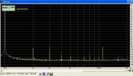
Measurement Equipment
This post describes the test equipment, which I used for the measurements regarding deadtime distortion.
The scope measurements have been done with an IWATSU Storagescope TS-8500 with 500MHz bandwidth.
Scaling will differ from the display, because the used probes where 1:10 and 1:100.
Effective scaling will be written in the post with the screen shot.
The distortion measurements have been done with an USB sound card, Creative E-MU Tracker Pre.
A slight upgrade of the card: OP amps changed to OPA2134, which improved noise a little bit and keeps drive distortion low even at load impedances of a few hundreds Ohms.
The attached measurement in this post is showing the limitations of the sound card itself.
Obviously this cannot compete with an AP2, but the worst errors of the sound card are in the range of -100db,
which is easily good enough to show the dead time distortion.
In front of the sound card input a simple passive 3rd order low pass with bandwidth of approx. 20kHz has been used,
in order to avoid irritations from the 400kHz carrier of the class D amp.
Attachments
- Status
- This old topic is closed. If you want to reopen this topic, contact a moderator using the "Report Post" button.
- Home
- Amplifiers
- Class D
- Are class D amplifier only good for subwoofer speakers ?