TAS5630 vs TDA8954
tas5630 have smart circuits, only single dc power supply necessary, but it need 4 sets of LC filters, cost high. performance better, power output are differential out, output signal better. no POP issue when drive subwoofer,sometime it is hard to drive it smooth with new learner.
Tda8954 need double dc power, circuits are a bit complex, but total cost is low.
I think TDA8950 should better, similar performance and very low price, 3.5usd/pcs enough for tda8950.
compare two chip ,it is easier to make stable amp with tda8954.
Could you kindly verify and comment on the choice of components for the TDA8954?
I intend to operate it on +/-40V. The reference designators follow the datasheet.
Any thoughts on the implementation of a power supply?
I was planning on making a +/40V; 6A, 12V;1A supply based on the NXP resonant SMPS topology.
The other thought was to use a linear power supply and use a CVT as a pre-regulator.
Can anyone comment if a step-down CVT can be made that will take 90-270Vac and give constant 28-0-28? This would be awesome!
Thanks in advance!
Attachments
Could you kindly verify and comment on the choice of components for the TDA8954?
I intend to operate it on +/-40V. The reference designators follow the datasheet.
Any thoughts on the implementation of a power supply?
I was planning on making a +/40V; 6A, 12V;1A supply based on the NXP resonant SMPS topology.
The other thought was to use a linear power supply and use a CVT as a pre-regulator.
Can anyone comment if a step-down CVT can be made that will take 90-270Vac and give constant 28-0-28? This would be awesome!
Thanks in advance!
you can show your schematic here, so diyaudio member can help u check it.
TDA8954 Sch and BOM is attached
Hello again,
Sorry, I had to figure out the approach I want to take and that took a while.
Can we start at the amplifier?
As per your suggestion, I have decided to go with TDA8954.
I want to eventually power it with +/-24V/ 10.5A supply.
We will come to the power supply part later.
In the attachment is the schematic that I will be using.
It is the datasheet application note from NXP. The values of the components are given. However the type of capacitors (ceramic, polyester, electrolytic etc.) is not given. I have made assumptions in the attached excelsheet.
Kindly take a look and advise.
Thanks in advance and regards,
bimbla.
Attachments
Audio input caps should be film type, through hole may be better in terms of microphonics
All power supply decoupling caps should be ceramic X7R and surface mount very close to pis of chip
All large value ripple filter caps should, of course, be electrolytic 105 degree temp and over rated voltage is best
The output filter caps should be high voltage poly film
The best output inductor I have found is ICE POWER or SANGAMI ferrous box shielded types
It would be a good idea to share your PCB layout before you commit to manufacturing it to get advice. I have produced several amps based on this series of chips and can help you.
Power supply for TDA8954TH
Can this supply power to power the TDA8954TH
Can this supply power to power the TDA8954TH
Hello again,
Sorry, I had to figure out the approach I want to take and that took a while.
Can we start at the amplifier?
As per your suggestion, I have decided to go with TDA8954.
I want to eventually power it with +/-24V/ 10.5A supply.
We will come to the power supply part later.
In the attachment is the schematic that I will be using.
It is the datasheet application note from NXP. The values of the components are given. However the type of capacitors (ceramic, polyester, electrolytic etc.) is not given. I have made assumptions in the attached excelsheet.
Kindly take a look and advise.
Thanks in advance and regards,
bimbla.
Hi
any one know a class D or T chip with 150 watt and 2 ohm load in output ?
thanks
TPA3251 or TPA3255 in PBTL configuration.
Hi Bimbla,
please could you help me to select the best output inductors for the TDA8954 based on your previous experience? I'm suffering a lot due to heating of them.
Thanks in advance.
Regards,
Juan Antonio Rodriguez.
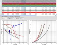
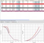
Make sure the inductor selected have sufficient current rating.
For lower distortion related to inductor choice select inductors with a flat inductance vs current graph.
For heating issues select ones with lower losses...both due to current and frequency effects.
Attachments
- Status
- This old topic is closed. If you want to reopen this topic, contact a moderator using the "Report Post" button.
- Home
- Amplifiers
- Class D
- TAS5630B vs TDA8954