PBTL output voltage swing is primarily given by battery voltage and should match your requirement independent of the chip you choose. I use TPA3118 w/o heat sink in 24V/50W application so this should run totally cool in your application. To minimize size you may consider an inductorless output as proposed by TI.
Hello, I just wanted to share a small hack to reduce the gain of a cheap chinese board with tl074 with minimal modification.
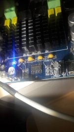
The tl074 use two opamp per channel, the first one in inverter configuration (with a gain of 10db on my board) the second one as buffer.
I added a 1k resistor in parallel with the 20k feedback resistor to lower the gain of the first opamp to -3db (nothing special in this value, I just happened to have two 1k resistor lying on my desk).
I hope this might help if you want to experiment, this modification is not as invasive as changing the resistors under the heat sink or removing the opamp.
Attachments
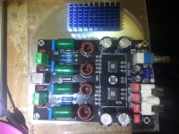
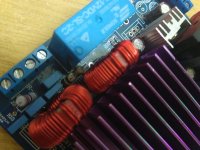
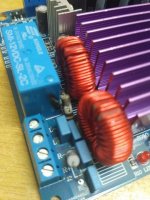
Hi guys, I designed a pcb with easyeda 2x tpa3116 2.1, assembled everything works perfectly but with 24v the inductors become hot after a few minutes... i thought that the inductors i chose are not suitable for tpa3116 as many people had the same problem and by changing the inductors the heat disappeared.
The inductors I am using are gods Eaton Dr125-100
Access to this page has been denied.
In your opinion, if you change them with Wurth the heat would disappear?
The inductors I am using are gods Eaton Dr125-100
Access to this page has been denied.
In your opinion, if you change them with Wurth the heat would disappear?
Use inductors rated for at least 7.5A before saturating, and with as low of a DCR as you can find within reason. CoilCraft, Wurth, Bourns, etc are good brands. The inductors should not get hot. Use the bootstrap snubber mod - treat might reduce the temps as well by preventing oscillation or ringing in the inductor. Also important to use a high quality output filter cap. Vishay, Wima, TDK, film cap rated at least 100v will work better.
Last edited:
I have a Fosi audio BT20A on it's way and totally forgot i have a 24 volt 10 a power adapter,supply.
Can i use it to get most out of the amp i 4 ohm, is there an overload protection ?
Stock is 24V 4.5A, for a dual based 3116D2 Nobsound TPA3116 D2 nobsound (2012 version) NS-G15 they say Max. output power: 100W+100W (above 24V@8A / 4Ω)
Can i use it to get most out of the amp i 4 ohm, is there an overload protection ?
Stock is 24V 4.5A, for a dual based 3116D2 Nobsound TPA3116 D2 nobsound (2012 version) NS-G15 they say Max. output power: 100W+100W (above 24V@8A / 4Ω)
Back to my amp its time to change some parts so for the 4 470uf caps i have Panasonic FR-A Series and Nippon Chemicon KYA Series both at 470uf/35V.
https://www.chemi-con.co.jp/en/catalog/pdf/al-e/al-sepa-e/004-lead/al-kya-e-2020.pdf
https://industrial.panasonic.com/cdbs/www-data/pdf/RDF0000/ABA0000C1259.pdf
Which brand to use?
My board has 1 ohm /1 watt resistors instead of the 3.3 ohm .Can i place 3.3 metal film 1/4 watt there?
https://www.chemi-con.co.jp/en/catalog/pdf/al-e/al-sepa-e/004-lead/al-kya-e-2020.pdf
https://industrial.panasonic.com/cdbs/www-data/pdf/RDF0000/ABA0000C1259.pdf
Which brand to use?
My board has 1 ohm /1 watt resistors instead of the 3.3 ohm .Can i place 3.3 metal film 1/4 watt there?
Attachments
i soldered the Nippon Chemicon KYA Series 470uf/35V.i wont do a switching test at the moment.Now i will modify the gain to be 26db. Why the datasheet suggests to use low leakage caps as input caps?For input caps i have 4.7uF Nichicon Fw Series which have standard leakage.Also i have 2.2uf Wima instead of the 3.3uf suggested for 26db gain.
Use inductors rated for at least 7.5A before saturating, and with as low of a DCR as you can find within reason. CoilCraft, Wurth, Bourns, etc are good brands. The inductors should not get hot. Use the bootstrap snubber mod - treat might reduce the temps as well by preventing oscillation or ringing in the inductor. Also important to use a high quality output filter cap. Vishay, Wima, TDK, film cap rated at least 100v will work better.
hi and sorry for interupting a little slightly off topic about class D ... last time i did some damage to the zobel resistor caused by no load connected to my TDA8950 and some oscillation happened at the preamp ... so if i were to add a dummy load (say 560ohm 10w resistor) and at that time should no speaker load is connected OR the speakers leads disconnected by accident(bad connection e.g.) will still the LC filter resonate and cause some damage around the choke filter area / zobel / integrated circuit or not? thanks

ok this is what happened past few years ago to my TDA8950 without any load connected to one of the channel and another one has a speaker load and it fried the zobel resistor ... i managed to fix it by replacing the resistor only and the amp is back to working ... so in order to prevent something like this by putting load resistor across unused channel will prevent such from happening? thinking to try it on my TPA3116D2
Attachments
I assume 560R will make no difference. There is no simple way to secure the zobel resistor except bw-limited input signal.
how about the flyback clamp diodes? i've heard some modules have them
The clamp diodes should limit the resonant peak to the voltage rails thus protecting the output filter capacitors and limiting current as well. These maybe your choice for tweaking an existing amp. The best solution imho is a suitable post-filter feedback that btw equalizes frequency response and makes the amp no-load stable.
You may look here:
Class-D with TPA3118 - An Update after all these Years
Class-D with TPA3118 - An Update after all these Years
No, your AUX input signal is transformed from analog to digital by the bt chip. Then it again converts it from digital to analog and outputs it. This won't work if the chip is not working. You should completely remove the chip. Especially since it doesn't work right. You can't disable the chip but keep it on board and still have normal AUX signal going to the amp.
I made some modifications on your picture. You need to remove the input cap and resistor imediately after the AUX jack. I have blacked them out. You also have to completely remove the BT chip. Best way is to use a cutter/small knife and cut the legs exactly where they come out of the chip, don't press too hard so your knife doesn't go into the pcb when the pins give. After you cut the legs all around the chip, remove the chip, then clean the leftover legs with the soldering iron.
After you remove the chip, solder two wires, just like the pink lines in the photo below. This should be the best solution, it will surely work fine, and you should theoretically have increased sound quality.
Only remove what I have blacked out.
edit: if the chip pads are too small to solder wires to them, then just follow the traces and solder the wires to the lower caps, that the traces go to.
I did this mod from post #11720 to get rid of the bluetooth chip and to avoid an unnecessary ADC conversion (I only need aux in) and hopefully get rid of some noise. However now I dont get any sound, not even a faint hiss. I've measured and made sure that there still is voltage to the amp chips, I also measured 2.6V on the mute pin.
From the tpa3116 manual: "12. Mute signal for fast disable/enable of outputs (HIGH = outputs Hi-Z, LOW = outputs enabled). TTL logic levels with compliance to AVCC"
It seems then that pin 12 should be grounded to un-mute the board? I tried to run a ground wire directly to pin 12 but it didnt help. Any ideas?
This is the board btw Bluetooth 5.0 High Power Amplifier Board TPA3116D2 Audio Module 2.1 Sound Channel Bass Super Bass Digi Amp 50W*2+100W|Amplifier| - AliExpress
- Home
- Amplifiers
- Class D
- TPA3116D2 Amp