Status:
Stereo channels work after being reworked back from PBTL.
Sub-channel negative side output (without filter choke) shows 9-10V.
Sub-channel positive side output (without filter choke) shows around 1.4V.
Correct?
Outputs from the TPA3116 when active but without an input signal should be close to half the supply voltage (12V) thus around 6V.
You measure 9-10V for one output and 1.4V for the other output. That is not what I hoped but it may be due to a measurement problem.
The outputs from the TPA3116 chip are PWM modulated at some 400KHz. Your multimeter cannot measure that directly. You need to low-pass filter the output signals from the TPA3116 before using your multimeter.
How to make a low-pass filter? A 10KOhm resistor in series with a 10-100nF capacitor. Connect the free end of the 10KOhm resistor to the TPA3116 output, the free end of the capacitor to ground and measure the voltage across the capacitor. Do you have a 10K resistor and a 10-100nF capacitor?
Before the output voltages from the TPA3116 are at the right level it makes no sense to connect a speaker because the speaker may be subject to a DC voltage that will overload the amplifier.
if you measure the output at the speaker terminals behind the LC-output filter there is little switching signal remaining so a regular DVM should do.
And obviously your DVM works correct at the working channel.
One output is hi, the other low. So I would assume there is some DC-error signal at one or both inputs.
Perhaps a faulty coupling cap. Are there MLCC coupling caps? If so, replace this crap by film caps.
And obviously your DVM works correct at the working channel.
One output is hi, the other low. So I would assume there is some DC-error signal at one or both inputs.
Perhaps a faulty coupling cap. Are there MLCC coupling caps? If so, replace this crap by film caps.
Last edited:
if you measure the output at the speaker terminals behind the LC-output filter there is little switching signal remaining so a regular DVM should do.
The problem of using the ordinary LC output filter is that a load is needed to dampen the filter and avoid over-voltage. As the outputs appear to have an important DC component between them, the outputs will be overloaded by the DC current and the undisturbed values cannot be measured.
If this was the problem, an 5~10R dummy resistor should do the trick.The problem of using the ordinary LC output filter is that a load is needed to dampen the filter and avoid over-voltage. As the outputs appear to have an important DC component between them, the outputs will be overloaded by the DC current and the undisturbed values cannot be measured.
In case of DC overheating the resistor, put in series a film cap 1uF - now you have a damping snubber.
Anyway, the symptoms described lead me to a DC input error.
Last edited:
If this was the problem, an 5~10R dummy resistor should do the trick. Anyway, the symptoms described lead me to a DC input error.
True, a dummy resistor would do the trick but also pull the outputs with the DC offset.
The DC input error is a logical assumption.
Situation: Both the stereo and PBTL sub-channel used to work. Then, the stereo TPA3116 chip on the same board was modified from stereo setup to PBTL configuration and worked. This modification of the other chip left this sub-channel chip to malfunction. Is there a link or are we just unfortunate that another fault appeared at the same time? A bit tricky with a board owner having only moderate diagnostic tools.
I assume some fault done by the user. Maybe some MLCC was mistreated and cracked? Some solder blob shorting IC-pins? There are myriades of possibilities....
You are terribly right. This is why I try to find a reference configuration from where we understand the measurements and can progress by adding functionality.
Very cooperative owner and precise in response. Just not a lot of tools. We will give it a try.
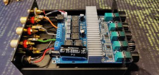
I recently had a reason to get me one of those TPA3116 2.1 boards. From the few choices I ended up with the one with most adjustments:
TPA3116 2.1 Digital Audio Amplifier Board HIFI DC 12-24V BASS Speaker 50W*2+100W 721968958942 | eBay
First test with a 19v laptop PSU wasn't very promising, there was hiss and buzz from every channel. The buzz disappeared almost completely when I touched the heatsink. After that I assembled the amp in an aluminium enclosure, hoping to get rid of some interference.
The hiss from main channels disappears when I turn the treble pot clockwise. But after that the buzz gets louder... not good.
The amp is connected to my pc via FX-AUDIO DAC-X6, first using the usb connection. I could pretty much hear every single thing that happens inside my computer. Tried to get rid of that with optical connection, but no good. The interference has to come from the mains network, because I also get sounds from my speakers when the freezer in the same room starts up. The freezer has safety earth, but the PSU doesn't.
I will try to get this working, so next steps are:
1. Test with another PSU
2. Test with other sources and computer without the DAC between
Any tips on the amp itself? Should I try to make some grounding between the board and the enclosure? I don't have any pcb stands in there at the moment, they would probably make some connection between them? At the moment the only connection is from the pots.
Attachments
Yes, a good quality PSU might improve it, but it's not a possibility here. I wan't to do this as small (and cheap) as possible, I have plenty of those laptop bricks.
Did try with a brand new Fujitsu OEM PSU but no improvement.
Took off the heatsinks to see what's going on under there, and will it make a difference; no. Well, at least the other chip is mute now, no output at all, don't know what happened
Only thing I noticed so far, that the SDZ and FAULTZ pins show nothing on the muted chip, while the working chip pins measure 16,7v. The pins are connected together, so the chip should recover from faults, right? Or is it fried now?
The output z of that laptop supply will not give kick-drum bass.
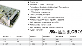
I use the tpa3118 mono boards and mount a few inches from MeanWell 24v 100W supply.
The little boards sound unbelievable, bass like a subwoofer.
yes i can agree - i use a different model - a cheap mean well LRS150-24V is not bad for 21euros over amazon
Yes, a good quality PSU might improve it, but it's not a possibility here. I wan't to do this as small (and cheap) as possible, I have plenty of those laptop bricks.
Did try with a brand new Fujitsu OEM PSU but no improvement.
Took off the heatsinks to see what's going on under there, and will it make a difference; no. Well, at least the other chip is mute now, no output at all, don't know what happened
Only thing I noticed so far, that the SDZ and FAULTZ pins show nothing on the muted chip, while the working chip pins measure 16,7v. The pins are connected together, so the chip should recover from faults, right? Or is it fried now?
Hi
You just use a different PSU and now a chip is set down --> not working anymore?
Hi
You just use a different PSU and now a chip is set down --> not working anymore?
Changing the PSU didn't do it. It worked just fine after that. Something happened when I took off the heatsinks.
Don't know where to begin with troubleshooting, I might leave the amp as it is and use it later for a small sub or something, because the other chip still works.
Changing the PSU didn't do it. It worked just fine after that. Something happened when I took off the heatsinks.
Don't know where to begin with troubleshooting, I might leave the amp as it is and use it later for a small sub or something, because the other chip still works.
The heatsinks were fastened with screws, not thermal glue?
Physical stress can damage the very thin PCB tracks.
My experience with a defect TPA3116 stipulates: Power off, speaker disconnected. Check with an Ohm-meter on the power supply terminals (red probe to supply "+", black probe to supply "-") if the impedance increases steadily to above 20KOhm. Then, measure the impedance from the two outputs (to the speaker) and to ground - any below 200 Ohm? Same from the two outputs (to the speaker) and to the positive supply terminal - any below 200 Ohm? And, between the two output terminals.
If no low impedance measurements -> speaker connected, no input signal and power on. Are the potential at the two speaker output terminals (to ground) around half the supply voltage and the same for the two terminals?
Thanks FauxFrench, I'll try to give it a go:
Yes, only screws
Supply connected to the board? And then measure from the supply post? I get some readings from the meter in ohm-scale, just quick flashes, but it doesn't have auto-scale. In 1k and 10k scale, nothing.
From power- and output:
-sw output: 16,8k
-left output: nothing
-right output: nothing
From power+ and output
-sw output: nothing
-left output: nothing
-right output: nothing
From output terminals:
-sw output: 33,4k
-left output: 67,7k
-right output: 66,4
Half the voltage in sw output, nothing on main channels.
The heatsinks were fastened with screws, not thermal glue?
Physical stress can damage the very thin PCB tracks.
Yes, only screws
My experience with a defect TPA3116 stipulates: Power off, speaker disconnected. Check with an Ohm-meter on the power supply terminals (red probe to supply "+", black probe to supply "-") if the impedance increases steadily to above 20KOhm.
Supply connected to the board? And then measure from the supply post? I get some readings from the meter in ohm-scale, just quick flashes, but it doesn't have auto-scale. In 1k and 10k scale, nothing.
Then, measure the impedance from the two outputs (to the speaker) and to ground - any below 200 Ohm? Same from the two outputs (to the speaker) and to the positive supply terminal - any below 200 Ohm? And, between the two output terminals.
From power- and output:
-sw output: 16,8k
-left output: nothing
-right output: nothing
From power+ and output
-sw output: nothing
-left output: nothing
-right output: nothing
From output terminals:
-sw output: 33,4k
-left output: 67,7k
-right output: 66,4
If no low impedance measurements -> speaker connected, no input signal and power on. Are the potential at the two speaker output terminals (to ground) around half the supply voltage and the same for the two terminals?
Half the voltage in sw output, nothing on main channels.
Many thanks.
As I understand, it is the main channels ("MC") chip that doesn't work while the SW channel works? If so, let's concentrate on the MC chip only.
You write "nothing". For impedance I understand this to mean high impedance while for voltages a low voltage near 0V. Correct?
You give an important information: The FAULTZ and SDZ pins are low which indicates the chip on startup sees a fault and mutes the amplifier on the SDZ-pin by pulling it down with the FAULTZ-pin.
What fault does the MC chip see (our quest)?
I find one strange measurement value among what you show: "-right output: 66,4". If that means 66,4 Ohm, it indicates an output problem. Is it 66,4 Ohm or 66,4 K?
For your impedance measurements to the "+" and "-" terminals from the output terminals, I only have half the values I expected. For the MC chip you have 4 output terminals: two for left channel and two for right channel. My experience from measuring on 7 defect TPA3116 is that one of the 4 output pins "hang" (short-circuited to) on either "+" or "-", typically "-".
I will kindly ask you to redo the impedance measurements, without speakers connected and no power. From all 4 output lines to "-" and from all 4 output lines to "+". May one be hanging?
If no output line is hanging, we will turn to the input pins. If one of the input pins are outside correct operational value, the FAULTZ will be pulled low. Lets see afterwards.
Last edited:
Thanks FF for the quick reply, I'll continue the research:
Yes. The SW chip works just fine.
That's right, my mistake. Nothing means zero voltage and high impedance.
It was 66,4k
Sure thing, and good that you asked. Now I'm getting totally different measurements. Does polarity matter in impedance measurements?
From power- and output:
-sw output1: 92k
-sw output2: 91,1k
-left output1: 102,5k
-left output2: 102,9k
-right output1: 101,7k
-right output2: 102,9k
From power+ and output
-sw output1: 112,1k
-sw output2: 112,5k
-left output1: 122,6k
-left output2: 122,7k
-right output1: 123,4k
-right output2: 123,1k
I don't get any readings from just the output terminals this time.
As I understand, it is the main channels ("MC") chip that doesn't work while the SW channel works? If so, let's concentrate on the MC chip only.
Yes. The SW chip works just fine.
You write "nothing". For impedance I understand this to mean high impedance while for voltages a low voltage near 0V. Correct?
That's right, my mistake. Nothing means zero voltage and high impedance.
I find one strange measurement value among what you show: "-right output: 66,4". If that means 66,4 Ohm, it indicates an output problem. Is it 66,4 Ohm or 66,4 K?
It was 66,4k
I will kindly ask you to redo the impedance measurements, without speakers connected and no power. From all 4 output lines to "-" and from all 4 output lines to "+". May one be hanging?
Sure thing, and good that you asked. Now I'm getting totally different measurements. Does polarity matter in impedance measurements?
From power- and output:
-sw output1: 92k
-sw output2: 91,1k
-left output1: 102,5k
-left output2: 102,9k
-right output1: 101,7k
-right output2: 102,9k
From power+ and output
-sw output1: 112,1k
-sw output2: 112,5k
-left output1: 122,6k
-left output2: 122,7k
-right output1: 123,4k
-right output2: 123,1k
I don't get any readings from just the output terminals this time.
No readings on output terminals must mean high impedance.
Polarity did not matter when I measured on the defect TPA3116. They were clearly shorted.
Your MC chip seems not to be defect but something is disturbing its operation.
We have to check the inputs:
Speakers connected, power on. What supply voltage do you use?
Pin 1 (MODSEL): What is the voltage here?
Pins 4, 5, 10 and 11: Voltages here? They are the four inputs and we can see it the bias circuits are activated.
Pins 6 and 7: What is the voltage here? They should both be around 7V (GVDD).
Pin 8: Voltage here? It is the MODE and GAIN deciding voltage.
Pin 9: Voltage here? Should be 0V (ground).
Pin 12: What is the voltage here? It is a mute input. The level should be close to 0V for the outputs to be enabled.
Pins 13, 14 and 15: What is the voltage here? Probably around 0V for 400KHz operation.
Pin 16: What is the voltage here? Does this pin seem to be connected to the other SW chip? One may be master and the other slave.
Then a few impedance measurements without power and without speakers:
Impedance between pin2/3 and supply "+"? We need to know that the pull-up resistor is intact, else it cannot start up.
Impedance from the four input pins 4, 5, 10, 11 to supply "-" and supply "+"? We need to know that all 4 inputs are free to settle according to the internal bias circuit. If even one of the are pulled high or low the chip will register "out-of-range" and disable with the FAULTZ signal.
Impedance between pin 12 and supply “+”? We need to ensure that the pull-up resistor is intact.
I know it requires some patience but such a chip has many inputs that may disturb operation.
When we know the values mentioned above, we pretty well know if the chip is treated correctly on the interface.
A last possibility is if another “intelligent” circuit may use the SDZ or MUTE inputs in a way we are not aware of. In such case, the disabling is of an external nature.
Last edited:
Hello
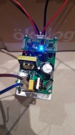
I recently bought a TPA3116 amplifier with built-in psu und bluetooth module.
It works well but without music it’s a bit noisy. Amp is always at 100% volume. When turn on and off you will get some plops on speaker.
It cost just less than 17$ shipping included.
I recently bought a TPA3116 amplifier with built-in psu und bluetooth module.
It works well but without music it’s a bit noisy. Amp is always at 100% volume. When turn on and off you will get some plops on speaker.
It cost just less than 17$ shipping included.
Attachments
- Home
- Amplifiers
- Class D
- TPA3116D2 Amp