With new preamp, it is finally as loud, as I wanted.
The low level of signal from subwoofer pre-out from AVR was certainly the problem.
Good to hear that. Is this the unit you got, and is the frequency control effective/fairly accurate?
Lusya Single Power DC 10 24V Low Pass Filter Bass NE5532 Subwoofer Pre AMP Amplifier Board with volume adjustmentA5 011-in Amplifier from Consumer Electronics on Aliexpress.com | Alibaba Group
With new preamp, it is finally as loud, as I wanted.
The low level of signal from subwoofer pre-out from AVR was certainly the problem.
Thanks for letting us know. A problem solved. Enjoy!
At the end, I found this DIY kit:
Velleman Kits K1803: UNIVERSAL MONO PRE-AMPLIFIER – Velleman – Wholesaler and developer of electronics
...and it performing good. Its gain is set by trimmer.
Currently I have it set at approx 30%.
Now its enough to set TPA3116 amp's volume knob to about 30-40%, to achieve the same volume level like it has before, when it was at 100% volume.
That Lusya preamp not arrived yet. When it arrive, I will have some preamp for the future projects at least")
I have order another TPA3116 amp with it, this one is PBTL mono only. Not like the previous one, which you can configure by soldering pads to 2x50W stereo / 1x100W PBTL mono.
And it have better sensitivity of 500mV. I am curious how it would perform without Lusya preamp, or with it.
Velleman Kits K1803: UNIVERSAL MONO PRE-AMPLIFIER – Velleman – Wholesaler and developer of electronics
...and it performing good. Its gain is set by trimmer.
Currently I have it set at approx 30%.
Now its enough to set TPA3116 amp's volume knob to about 30-40%, to achieve the same volume level like it has before, when it was at 100% volume.
That Lusya preamp not arrived yet. When it arrive, I will have some preamp for the future projects at least
I have order another TPA3116 amp with it, this one is PBTL mono only. Not like the previous one, which you can configure by soldering pads to 2x50W stereo / 1x100W PBTL mono.
And it have better sensitivity of 500mV. I am curious how it would perform without Lusya preamp, or with it.
Last edited:
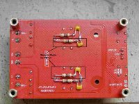
If this board is run in PBTL mode then do we need 4x the bootstrap components or should they be reduced to 2x? I mean 2x10ohm+2x330pF.R=4x10 ohm, C=4x330 pF
Capacitors are connected to PCB ground plane after scratching the paint in two points.
By the way, a piece of 2.54mm strip contact can be used as input connector (can be seen in first picture)
Any thoughts on that guys? Also isn't just easier to use the -ve terminal of the big caps for connecting to ground instead of scratching the board surface to access it?
Attachments
Last edited:
If this board is run in PBTL mode then do we need 4x the bootstrap components or should they be reduced to 2x? I mean 2x10ohm+2x330pF.
Any thoughts on that guys? Also isn't just easier to use the -ve terminal of the big caps for connecting to ground instead of scratching the board surface to access it?
I cannot trace the fulvio posting and get a full understanding but 10Ohm+330pF seem not to be bootstrap elements. With these values, they appear rather to form a Zobel element. In such case one set should do.
Thanks again FauxFrench, sorry I used the wrong term, its something related to R-C snubbers & not bootstrap elements. It's from post#9618 & #9621 from this thread.
So I would just need to "not" add the extra ones that I highlighted in the attached image above correct? Just double checking
So I would just need to "not" add the extra ones that I highlighted in the attached image above correct? Just double checking
So I would just need to "not" add the extra ones that I highlighted in the attached image above correct? Just double checking
You have better people on this forum than I concerning stability compensation of amplifiers.
The Zobel network serves to compensate for the voice coil inductance and stabilize the amplifier: https://www.eetimes.com/document.asp?doc_id=1274906 . As the speaker load does not change and the stability margin of the amplifier is little affected from change of BTL to PBTL, I see no reason to change the Zobel network.
If the 10Ohm and 330pF serve as a snubber, the snubber is there to damp ringing from inductive elements. Also the inductive elements are not changed such that the same snubber values can be assumed valid for those inductive elements in use.
This is my reasoning.
Last edited:
I cannot trace the fulvio posting and get a full understanding but 10Ohm+330pF seem not to be bootstrap elements. With these values, they appear rather to form a Zobel element. In such case one set should do.
TPA3116D2 Amp
Many thanks. They are snubbers. I see no reason to change the values.
I just grabbed one of these to drive a cheap "60W" 8 ohm home theater subwoofer that I dug out of storage-
http://a.co/d/2AhU1lS

Any known issues that I should worry about? It has a built in low-pass that I may have to change parts values on but I think it should otherwise be a cheap-and-cheerful solution to driving my sub.
http://a.co/d/2AhU1lS
Any known issues that I should worry about? It has a built in low-pass that I may have to change parts values on but I think it should otherwise be a cheap-and-cheerful solution to driving my sub.
Im trying to modify my 2.1 board and would appreciate some help.
First of, is it possible to make the BTL chip output in mono without cutting traces and solder directly to the chip?
Secondly, i want to either raise the cutoff frequency in the low pass filter or remove it totally, whatever is easiest since i dont really care about the filter.
I believe that the two resistors are at 47k and the two capacitors are at 0.068uF in the sallen key filter which gives me a cutoff frewuency at 50hz(?), would it be possible to change the two capacitors to 1nF to raise the cutoff to 3.5khz?
Basically what i want to do is to convert the board to a 100+100 w mono board in the easiest way. I already have this board and would rather not wait a month for a new one if it is possible to convert it.
Correct me if im wrong about anything, im new at this.
Attachments
I just grabbed one of these to drive a cheap "60W" 8 ohm home theater subwoofer that I dug out of storage-
http://a.co/d/2AhU1lS
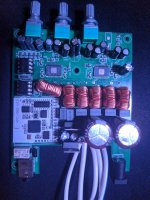
I am really interested how the board will perform in terms of noise. The route all the way around to the pot + output inductors right next to the input stage... It may work fine, I am just wondering if it will have any effect.
Thanks for reporting.
Im trying to modify my 2.1 board and would appreciate some help.
First of, is it possible to make the BTL chip output in mono without cutting traces and solder directly to the chip?
Basically what i want to do is to convert the board to a 100+100 w mono board in the easiest way. I already have this board and would rather not wait a month for a new one if it is possible to convert it.
Correct me if im wrong about anything, im new at this.
It is as such possible without working on the chip pins. The difference between BTL (stereo) and PBTL (mono) configuration is described in the datasheet, section 7.4.1.
For the jumpers at the output side, you can make these connections at the PCB pads for the filter chokes.
For the input side, you have to work on the small PCB pads for the input coupling capacitors (SMD I believe). The capacitors should be removed and the PCB pads toward the TPA3116 chip connected to GND. This is a bit more delicate but possible.
Last edited:
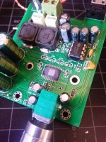
Well, running off of a 24 volt power brick, this board works better than expected. Output power is limited by the 8 ohm subwoofer that it's connected to (which is enthusiastically 60 watt rated anyways) but it sounds good. It's dead silent without signal, and is barely warm after blasting the sub for an hour. It has a summed input from stereo, and a built in low-pass at 180hz, which is too high, in my opinion. I'm using it with a two way crossover set for ~ 80hz or so, so it's not a very big deal really. I might try and reverse engineer a schematic for the low pass in it, to see what values of caps would work for a lower cutoff frequency.
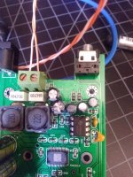
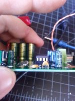
I pulled the heatsink and cleaned off the thermal compound, and replaced it with Arctic Silver 5.
Also shown- one of the low pass caps was bent over pretty heavy to clear the heatsink. If modifying things they may need to be wired off board. They are 100nF, but the board is marked for 68nF. The filter resistors look to be 47k.
Attachments
Last edited:
Well, the manufacturer states explicitely that the compound is not electrically conductive Arctic Silver Incorporated - Arctic Silver 5 . Some CPUs have resistors on the top and a conductive compound would be quite dangerous.
- Home
- Amplifiers
- Class D
- TPA3116D2 Amp