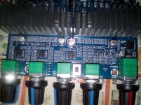
In found this 2.1 board that looks nice to me: good inductors and capacitors I think. I consider to use two of these board for a 3 way active system (one board per side). With this appliance there is a big difference between left and right channel (tweeter and woofer). Is this a problem for this kind of amplifier? Besides I am uncertain about the input. This is a jack for three channels?
I'm very familiar with this board having reverse engineered it and modified it to suit my needs.
The LP filter is fixed but can be modified to suit by replacing to box poly caps with different values. The sub channel also has a 1st order HP filter at 24 Hz, again, that can be lowered by replacing too caps.
Noasds noise floor is fixed by replacing 50K pots with 10K pots (I didn't have a problem running on batteries).
Here's a link to the boards analysis and a schematic of the signal paths.
The Nenola has a point. You can only input two signals into this board as the sub channel is combined from the L-R inputs.
Then this board doesn't suit me. I need three unfiltered channels. Too bad, the output filter looks really nice and is scarce in this type of board.The Nenola has a point. You can only input two signals into this board as the sub channel is combined from the L-R inputs.
Then this board doesn't suit me. I need three unfiltered channels. Too bad, the output filter looks really nice and is scarce in this type of board.
Your in rough waters. There's very few 3 channel amps. And combining three digital mono amps in close proximity is prone to inter-amp interference (switching frequency). To do that, you need to mod the boards to use the master and slaves option and run a clocking link from the maser to the slaves. There is a a nice, compact mono Sanwu TPA3118 1 x 60 W board for USD$5 each. But I haven't modded it to advise.
Yes, I agree mono amps should be a better solution in my case. Many of these amps are available for even lower prices. But I rather buy boards for a few euro's more I don't have to mod. Any advise on this?Your in rough waters. There's very few 3 channel amps. And combining three digital mono amps in close proximity is prone to inter-amp interference (switching frequency). To do that, you need to mod the boards to use the master and slaves option and run a clocking link from the maser to the slaves. There is a a nice, compact mono Sanwu TPA3118 1 x 60 W board for USD$5 each. But I haven't modded it to advise.
The amplifiers will be used in an active system and are used for mid and tweeter. So 50 W for mid and 25 W for tweeter should be sufficient. For the woofer I already have Hypex UCD 400. My intention is to integrate the amplifiers with the speakers. The streamer/active system is at a central position.There's some possibilities ... but need more info.
What type of power are you looking for? 8 ohm or 4 ohm drivers? Will the amp be separate or are you building two active speakers with an amp embedded in each?
Which frequency should I use to determine the impedance of the speakers, the minimum, average or maximum? The minimum is somewhere around 5-6 ohm. Options for power supply are 0-24V and -35-0+35V
Last edited:
That's easier. You only need two channels, one for the mid and one for the tweeter as you have a separate amp for the woofer. You 5-6 Ohm minimum impedance implies nominal 8 ohm woofers. At 24 volts, you can get 33 W rms into a 8 ohm driver regardless of amp rating. If you had a 4 ohm mid, that would increase to 65 W rms with a 24 V PS. There are a myriad of 2 channel TPA3116 class D amp boards that will do that.
Hi guys. I'll take this.
Free ship Assembled HIFI digital power amplifier TPA3116D2 2.1 high power board 12 24V subwoofer bass board-in Amplifier from Consumer Electronics on Aliexpress.com | Alibaba Group
But this cuts satellites from 100 hertz, how to draw from 150-200 hertz. Someone had experience with this? Show me the picture that I need to change to make 150 Hertz?
Attachments
I have two of these and both failed, now one channel, later the two, and the same with the input DC. I found that the failure is produced by the tracks of the PCB. All connections failed. I put a wire bridge from the positive DC to diode and connected the output of speakers directly from the output of the capacitors under the PCB. Doing all that the amp is functioning and at a very high degree of performance. The sound is very good and no hiss nor hum (proved in different speakers from 4 to 8 Ohms without modifications). I use an SMPS of 24V 15A and no interference at all.
Also, no click at on like you say.
So, surely the problem isn't in the input side of audio, is on input DC and is on output of speakers. The two amps that I have did the same.
I know that it's two years later but if this can help other to repair this amps ...
Also, no click at on like you say.
So, surely the problem isn't in the input side of audio, is on input DC and is on output of speakers. The two amps that I have did the same.
I know that it's two years later but if this can help other to repair this amps ...
I bought the red dual chip board and the right channel didn't work.
2X100W TPA3116 D2 Dual Channel Digital Audio Amplifier Board 12V 24V for Arduino | eBay
There is a faint click upon turn on and the left channel does that but there's nothing on the right. I tried switching speakers and it's the same. If it is bad connector, most likely the right channel would be noisy or something like that. But this is nothing at all. Could it be the pot, female 3.5mm socket, or the chip itself?
I have 2 of these boards and they are great. I noticed that the board in your link is missing the full range/ 100hz (?) HP filter switch for the tops.Hi guys. I'll take this.
Free ship Assembled HIFI digital power amplifier TPA3116D2 2.1 high power board 12 24V subwoofer bass board-in Amplifier from Consumer Electronics on Aliexpress.com | Alibaba Group
But this cuts satellites from 100 hertz, how to draw from 150-200 hertz. Someone had experience with this? Show me the picture that I need to change to make 150 Hertz?
Where did you find / how do you know that is cuts at 100hz and why would you like to change it? If your tops are not producing much down 150/200hz (like mine) a bit more overlap in the 100-200hz is not a real problem. The 100hz cut keeps the top drivers from reaching xmas for the low frequencies wel enough for most speakers. It would have been nicer if it would have been variable as well; but for the money........... I paid a little less on ebay.
Last edited:
I don't know what the problem would be as they are seperate amps.Ok, It will not be a problem that these ICs will not be synchronized?
Does any see a problem with using 2 class D boards for tops and sub?
I don't know what the problem would be as they are seperate amps.
Does any see a problem with using 2 class D boards for tops and sub?
http://www.diyaudio.com/forums/clas...audio-application-beat-tones.html#post5346454
Other amplifiers same problem
Both amplifiers are connected by the input too. I don't know how beat tones sound and if they are measurable. I have tested two class D amplifiers in parallel but heard nothing special. Besides I have a Hypex as100d with an additional class d amplifier for bass. In that combination I have some low noise but I think thats a grounding problem.Thx, is this a real world or more a theoretical problem?
From that thread: "As far as I am aware this is only when two amplifiers are connected to the same power supply. Otherwise it really doesn't matter."
Thx, is this a real world or more a theoretical problem?
From that thread: "As far as I am aware this is only when two amplifiers are connected to the same power supply. Otherwise it really doesn't matter."
Personally for convenience I'd assume it's a theoretical problem and just go ahead.
The proof is in the pudding - try it the way you originally set out to do it, and *listen*.
Only if you find you don't like the sound and think this specific issue might be causing it, deal with it.
It's no use chasing a sound that's always around the next corner just because you've read something somewhere.
DIY is buy and try and fly or cry
")
Over at PE's TechTalk it has happened. Depends on the amp (perhaps the robustness of the output filters).
The combination of two tones produces two other tones of F1-F2 and F1+F2. Two separate amplifiers have two distinct clocks (even if they're set for the same frequency there is +- tolerance on the clock). This can lead to beat tones.
A good example is a twin engine airplane flying over head. YOu can hear the F1-F2 frequency as the rising and falling volume of the overall drone of the engines.
quick question - when using shielded cable for the input wires, the shielding should be connected on one end only, to the ground of the psu, right?
That's the old rule-of-thumb based on proper design.
Explanation:
Many AC power cords are three prong: Live, Neutral and Ground. Ground should only be connected to a device's metal enclosure to meet safety requirements, never to any circuitry /signals. Most older equipment's circuitry was isolated from AC power via it's power supply transformer. So all the electronic signals / connections are isolated from the AC power feed and AC ground.
When you feed a signal from one device to another, you connect the signal plus and signal ground on each. Both devices are floating with respect to their ac feeds (via the PS transformer isolation). Thus, no extraneous current can flow between them; only the signal(s) will flow.
But if you connect the shield to the chassis ground at both ends, you've now connected ground from two different AC feeds via the chassis grounding. You have created a ground loop. That will likely cause problems as current can flow from one ground to the other. Therefore, you connect the shield to the chassis at one end to ground it, and not the other to avoid a ground loop.
Note: not all manufacturers equipment designs implement this grounding correctly. And some have problems.
Same goes for a modern device with a switching power supplies . However, some supplies, like laptop bricks, connect their DC ground output back to the AC ground. So two devices with that type of supply will have a ground loop by default. And many/most are not isolated, another source of potential problems.
Last edited:
I received two of these boards this week NEW TPA3116D2 Dual channel Stereo High Power Digital Audio Power Amplifier Board 2*120W in NEW TPA3116D2 Dual-channel Stereo High Power Digital Audio Power Amplifier Board 2*120W van Versterker op AliExpress.com | Alibaba Groep
Unfortunately no RCA connectors and the wire was assempled wrong (left/right reversed). I hooked them on a power supply of 24 V. The sound quality is very well, a little bit reluctant in the high compared to other amplifiers. The board is sold as a 120W baord but to be honest I don't think this is true, there is only one chip under the heatsink.
Unfortunately no RCA connectors and the wire was assempled wrong (left/right reversed). I hooked them on a power supply of 24 V. The sound quality is very well, a little bit reluctant in the high compared to other amplifiers. The board is sold as a 120W baord but to be honest I don't think this is true, there is only one chip under the heatsink.
I received two of these boards this week NEW TPA3116D2 Dual channel Stereo High Power Digital Audio Power Amplifier Board 2*120W in NEW TPA3116D2 Dual-channel Stereo High Power Digital Audio Power Amplifier Board 2*120W van Versterker op AliExpress.com | Alibaba Groep
Unfortunately no RCA connectors and the wire was assempled wrong (left/right reversed). I hooked them on a power supply of 24 V. The sound quality is very well, a little bit reluctant in the high compared to other amplifiers. The board is sold as a 120W baord but to be honest I don't think this is true, there is only one chip under the heatsink.
I have a similar looking board also claimed to be 2x120 W (but I haven't pulled the "stick-on" heat sink to check. Mine also has bluetooth.
First, that 120W per channel rating is only possible at 24 V with 2 ohm drivers (and one chip can;t handle two per channel).
On mine, the bluetooth daughter board beings to minimize base starting at 100 Hz and it is down -3 dB at 30 Hz. This is measured right out of the bluetooth daughter board feed to the TPA3116(s). I'm guessing that the particular daughter board's BT chip (CSR8536) on board equalizer was programmed to minimize the low end as you wood for small $10 speaker phones where their tiny drivers can;t handle low freq. Also, the BT range using the PCB type antenna is 12' line-of-site. I'm experimentating with adding a "rubber ducky" type antenna this weekend.

- Home
- Amplifiers
- Class D
- TPA3116D2 Amp