I know what this chip can do. I have several at home and tested them with a regulated power supply. Yes I exceeded the ti specs. For a short time till they shut down. With large heat sinks they can run at rated output for quite a while till all the components get warm.
If I made a commercial product I would not advertise that product as exceeding the manufactured specs. I would not buy a Chevy malibu, repaint it and say it could do 0 to 60 in 3 seconds. Maybe the Chevy could, down a steep hill with a strong wind assisting being pulled by a Ferrari.
From the ti data sheet
up to 100W / 2 Ω in mono
I had a buddy who complained his amp could not play as loud as it should without shutting down. I tested it for him and told him it was fine. He still complained. I went over to his place and the amp was sitting on a shelf on top of a hot water radiator. It was winter. The amp was toasty hot powered off.
I had a buddy who complained his amp could not play as loud as it should without shutting down. I tested it for him and told him it was fine. He still complained. I went over to his place and the amp was sitting on a shelf on top of a hot water radiator. It was winter. The amp was toasty hot powered off.
Good point. In my (large) boombox that runs on the beach a high volumes for hours on end, I'm running 80 W through a 4 ohm driver on a PTBL sub channel. That doesn't exceed spec. but I ensure that it is in the shade given the summer heat and the sun's rays. I also pointed the woofer port at the chip's heat sink.
And I reiterate from my previous post ...
However, the thermal limitation is based on a continuous sine wave. Music is never as dense - maybe 1/2 to 1/3 as dense as a sine wave. And the dynamic peaks that would reach 120W not 150 W are short lived. The chip / heat sink combination has thermal inertia that can dissipate the peaks before the thermal threshold is reached.
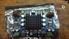
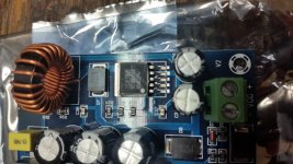
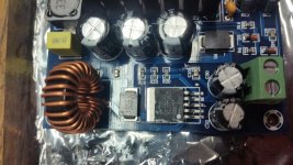
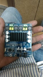
TPA3116 board with integrated dc/dc boost PSU
I have received the board I referenced in the previous post. I can confirm that there is in fact a dc/dc boost circuit built into this TPA3116 board, as I have taken the heatsinks off to check the chipset.
There are twin XL6019E1 on either side of the board as the drivers for the boost circuit.
Twin XL6019E1 - Inverting DC/DC Converter
Datasheet PDF for the XL6019:
XL6019E1 pdf, XL6019E1 description, XL6019E1 datasheets, XL6019E1 view ::: ALLDATASHEET :::
The two XL6019 could theoretically boost 12v to 24v at 5a each, giving this board a max PSU of 24v at 10a. That's a 240w boost power supply I doubt the pathetic heatsinks would support that amount of power though. Haven't had a chance to really test it yet, but I will report back with supply voltage to the TPA3116 as well as wattage out. Again, I doubt you could get 150w out of this board at all, at least without WAY more serious heat dissipation.
Attached are several pictures of the board in question. Always open to ideas and input...
Cheers,
Attachments
I think you've misread/misunderstood the listing; the power input is recommended to be between 12v and 24v. There is no step-up...
There is indeed a step up, please check my previous post above.
cheers,
Sorry for the multiple posts, but here is the current listing:
DC12V 24V 150W TPA3116D2 Mono Channel Digital Power Audio Amplifier Board car | eBay
cheers
DC12V 24V 150W TPA3116D2 Mono Channel Digital Power Audio Amplifier Board car | eBay
cheers
It seems that the original Sanwu TPA3118 board is no longer offered on Sanwu site.
Bluetooth Audio amplifiers
Bluetooth Audio amplifiers
I ordered the Sanwu tpa3118 board through The Sky One store on AliExpress however they sent the generic board not printed as Sanwu. Is there actually a difference and who sells the genuine Sanwu board?
All of the blue mono TPA3118 boards I have seen appear to have identical parts, though the print and board color seem to vary somewhat. I don't think it is a problem not having SANWU on the back of them. Many sellers show the SANWU board and send one without the printed logo on the back, just the way it is, no guarantee if the picture they post shows it, just get the cheapest.
Hi!
I would like to build a 3 or 4 channel amplifier with balanced inputs. I heard XH-M189 sound. It was very nice.
1Pc TPA3116D2 2x50W Dual-Channel Stereo Audio Digital Amplifier AMP Board | eBay
Can I do a modification for balanced inputs?
Can I make a connection for sync that amplifiers?
Are there any schematic for this board?
(Sorry for my terrible langauage )
)
I would like to build a 3 or 4 channel amplifier with balanced inputs. I heard XH-M189 sound. It was very nice.
1Pc TPA3116D2 2x50W Dual-Channel Stereo Audio Digital Amplifier AMP Board | eBay
Can I do a modification for balanced inputs?
Can I make a connection for sync that amplifiers?
Are there any schematic for this board?
(Sorry for my terrible langauage
)This has become quite a popular thread!
I have seen the following:
TPA3116D2 120Wx2 Digital Bluetooth 4.0 Audio Receiver Amplifier Acrylic Case DIY | eBay
discussed herein and the reviews are fairly positive. Obviously, there are many versions of a 3116D2 implementation but as with most chip amps, smaller is usually better. With that in mind, has anyone experience with:
DC 12V 24V Mini TPA3116D2 2x 50W Digital Audio Power Amplifier Board Class D Amp | eBay ?
The lack of capacitance on the board would seem to make it bass deficient at first glance but if the caps cycle quickly, it may be able to deliver the current required. Thoughts?
Hi all,
first, excuse me for my bad english
That's my first post here.
I have a blue-black TPA3116D board modded according most of the info in this topic.
I've made the following changes:
- DC Power Caps -330uf Panasonic "OSCON" caps.
- Input Signal DC De-coupling Caps - 1.0uF / 250V Wima MKP10
- Output Filter Inductors: Bourns 10uH toroid inductors
- completely remove one (maybe master) resistor. I found this info in some other topic.
- Snubber mod also is done according
- Output Filter Capacitors - TDK FK20X7R2E224K .22uf (I didn't remember what brand they were, also were changed with better ones)
I get the board from Ebay just to hear how sounds this chip.
My first impression was that it sounded terrible.
The height frequencies were very bad. The bass sounded somehow artificially and the mids were very colored.
Overall sound was somehow tense (maybe too much gain or fake chip, I don't know)
So I found the topic with mods and decide to try what will happen.
In fact there is overall sound improvement.
After modifications appeared more high frequencies, the bass become more real, a some scene appeared etc.
But still is hard to tell that the sound is good (by my opinion).
The bass is not too much even is slightly weak especially in the lowest region.
The solo drums and the mids sounds a little aggressive and the heights also are not very good.
The main problem is that it sounds a little colored and muddy. I don't know how to explain it better.
For example, when I tried to get more bass from Hifimediy T1-M with changing the input capacitors with bigger ones (i think 2.2uf vs original 1uf) the bass become more but the overall sound become "colored" with too much bass not lower, just too much. Especially noticeable in the vocals.
This is the closest example which I can give for the sound.
I've tried few laptop power supplies and cheap "low noise" switching power supply from ebay with step down module.
I tried different voltages (19, 21, 24) and maybe is truth that sounds best around 19V. Just sound more clear instead on 24v.
The Hifimediy feeds with the same power supply and the sound is much much better in comparison with the modded board.
Just sounds very nice, maybe a little bright but great
My plan was to use the TPA3116 to power a pair Overnight sensation speakers but.. if I can't find a way to make it sound better will look for other solution.
I get a cheap ebay 2.1 board with TPA3116 for a future project but it fails after test listening and there is no any sound now.
Seems it will sounded better in regard to the voices. I thing the sound was no muddy and colored in this way. Is hard to be sure because it was a very short listening. The seller promised that will send me a new board and still waiting
The 2.1 amp sounded a little "thicker" in comparison with TK2050 and LM1875 (for example) but I thing the sound wasn't "colored" as the sound from my modded board.
I don't know what is the reason, maybe the chip is fake...or something other..
My knowledge in schematics and the electronics are very basic so I don't know what to do or to try to improve the sound.
As I wrote I've tried different power supplies, with or without volume pot, I also tried to listen with preamp but the result was a little more bass, worse detail and more colored sound.
Here is the picture of the current configuration:
Get a descent TPA3116 board, for example directly from Sanwu, TPA3116 50W*2 digital amplifier board PBTL 100W mono power amplifier
If it still doesn't sound good, give up on cheap boards and get a good TPA325x board or at least a Sure board. Se other threads in this forum. There is no way an ugly duckling will ever be a class D swan.
If it still doesn't sound good, give up on cheap boards and get a good TPA325x board or at least a Sure board. Se other threads in this forum. There is no way an ugly duckling will ever be a class D swan.
I have used 3116d2 and also tpa3251. The latter is far superior. Better still go for TI evaluation board for 3255.Get a descent TPA3116 board, for example directly from Sanwu, TPA3116 50W*2 digital amplifier board PBTL 100W mono power amplifier
If it still doesn't sound good, give up on cheap boards and get a good TPA325x board or at least a Sure board. Se other threads in this forum. There is no way an ugly duckling will ever be a class D swan.
There is no point in wasting efforts on 3116/8.
Comments to dellame question.
You show an Ebay TPA3116D2 mini board. I have a similar TPA3116D2 mini board with a slightly different layout. But, I haven't had time yet to implement and test it.
I believe that such mini boards, or basic-boards as they may be called, are made with the philosophy that we provide you with the chip and the minimum configuration components, produced cheap with robotized SMD technology, and you add whatever you prefer for the more costly parts (output filter, decoupling capacitors, heatsink etc.). Not a bad idea considering that I often replace more of the initial components anyway when I buy a complete amplifier board.
Almost all class D boards I buy (monolithic) are supplied with too little decoupling capacitance (expensive and bulky). Clearly the same apply for the basic-board you show. But, that is not a problem because you can add what is missing of decoupling capacitance just outside of the basic-board power terminals. The little decoupling you have on the basic-board is sufficient to ensure that the chip is not oscillating. The remaining (external) buffer capacitance will fill up your on-board decoupling in microseconds when the voltage starts to drop. So, the worry about sufficient decoupling to ensure good bass can be solved.
The basic-board has obviously got no output filter and you can design your own to be connected at the basic-board output terminals.
I cannot see for sure, but, small ceramic SMD capacitors are probably used for signal coupling at the input. They should be removed/shorted and replaced by foil capacitors located just outside of the basic-board input terminals. So far - so good.
Cooling - here may be a problem: Close to each end of the TPA3116D2 housing are some rather big chip capacitors located. These ceramic chip capacitors seem thicker (measured from the board surface) than the TPA3116D2 housing. Thus, it will be very difficult to mount a heatsink on the cooling pad of the TPA3116D2 housing because you will hit the ceramic capacitors before touching the TPA3116D2 cooling pad. Hence, cooling of this basic-board is a problem. Unless you intend to use the board for low voltage operation (up to 15V), you will need a heat-sink. The designer did not take that issue into account.
Using such methodology you can foresee what you can do with the board from just a photo.
The TPA3116D2 basic-board I bought allows for a heatsink to be mounted. Else, it is probably a very similar quality as the one you show.
Last edited:
FauxFrench
Thanks for your attention. Some answers and some questions:
I'm assuming you were looking at the second board linked which is all SMD. The TPA3116D2 chip has the highest profile on the board so you can fit as large a heatsink on it as you like. An old CPU heatsink seems like a perfect match if I don't mount higher profile film caps on the same side. Will the larger foil capacitance with longer leads you suggest be better than the ones already there? It's hard to say at this point, I'll know more tomorrow after they're delivered.
Comments to dellama question.
Since my early days in electronics I have always been told to use foil capacitors in the signal path. This, because the foil capacitors are very linear, the ceramic X5R chip capacitors absolutely not, and X5R ceramics is highly piezo-electric and works like a microphone for mechanical vibrations. Therefore, I always try to replace the input coupling capacitors (often ceramic SMD types) with foil capacitors. As the ceramic chip capacitors are very small I normally remove them, make a short-circuit and arrange the foil capacitors at the input terminals.
Have fun tomorrow.
- Home
- Amplifiers
- Class D
- TPA3116D2 Amp