Referring to my post #9485:
- waveform at OUT+ and OUT- (referred to ground) are terrible (see pictures in post #9485);
- waveform across the load (difference between OUT+ and OUT-) is much better;
- at 10 W output power, signal frequency 6300 Hz, power supply 24V, third armonic across the load is 36 dB below the fundamental;
- in the same conditions, I measured the third armonic level before the output filter, that is at the TPA3116 output, finding it is 45 dB below the fundamental, better but not so good;
(for these measurements, I used a balanced input selective voltmeter).
So, assuming that TPA6116 is not defective (could be a fake?), I suspect the problem is due to the saturation of the inductors (stock little square ferrite type, but with 33uH).
Does anybody have a suggestion?
In case I'll decide to replace the inductors, what components should I use, assuming I don't want to spend more money for the new inductors than the cost of the whole board?
Is it worth to try these ?
5pcs Toroid Core Inductor Wire Wind Wound for 22uH 3A | eBay
Standard could be like 10uH/1uF or 10uH/680nF, 4 to 6 ohm. Standard 8 ohm would be 22uH/680nF, 33uH/680nF would be 10 ohm.
33uH has lower filterfrequency, so peaking could be audible if speakerimpedance is much higher
Hi, 33uH, 0.68uF and 8 ohm should form an overdamped filter, so it causes a loss, not a peak, at high frequency; in my board (that uses these values), I measured a loss of 1.2 dB at 20 KHz.
But you are saying that a speaker could have an impedence higher than 8 ohm at the filter resonance, so it could have a large peak: it is true, but I think this can happen in any case, whichever are the filter components; maybe it's better to try to compensate the speaker impedance (inside the speaker).
What I am worried about is that the higher is the inductance, the lower is the saturation current (for the same core); I'm afraid this is the reason why I measure so high distortion in my board (see post #9500).
You have more excessive peaking below 20kHz with 30kHz filter(33uH) than with 60kHz (10uH) filter when it peaks at those frequencies. You don't have that problem when you create a near constant impedance, like the resistor you used to watch the overdamping. Speakers usually have rising impedance
You have more excessive peaking below 20kHz with 30kHz filter(33uH) than with 60kHz (10uH) filter when it peaks at those frequencies. You don't have that problem when you create a near constant impedance, like the resistor you used to watch the overdamping. Speakers usually have rising impedance
You are perfectly right. What I mean is that if you add a Zobel network to the speaker, you make its impedance constant, so you don't have to worry about peaking (constant impedance is better also for class A or class AB amplifiers).
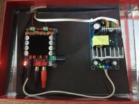
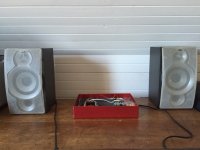
So this board eventually arrived - well delayed by our postal authorities. It looks to be genuine Sanwu, nicely made with a very odd input/power/output configuration. Plastic stand-offs/feet and a volume knob were included with the board. The package took a hammering (2 months in transit) but the components were really well packed and reached me unscathed. I've hooked it up to the SMPS that I got from the same seller, and connected a pair of JVC speakers from a micro/mini player, the amp of which expired some years ago.
I don't have the linguistic skills to explain depth, speed, sound stage etc, but to me, it sounds excellent. The JVC speakers are rated at 6ohm, 45w I think, and the amp drives them cleanly and with way more volume than I'll ever need. I'm using a laptop stocked with MP3s as the source, took a bit of bodging with the integrated equalizer in WMP and it now sounds great.
I put the board and SMPS box in a conveniently-sized box for now, the cable routing is obviously not optimal, but it works well and I don't get any bad noises apart from a bit of a hiss if I really wind the amp up with source attached but not playing. Considering the component cost and the crappy source, I'm well impressed.
Attachments
Hi, today I’ve got my first TPA3116 board, the dual chip XH-M190 v.3; it was configured in the master/slave mode, with 26 dB gain for each channel.
The SYNC pins of the two chips were connected via a R-C with the wrong values (10 Kohm and, I suppose, 1 nF) so the sync signal at the slave side was near to zero.
The master chip was switching at a frequency of about 400 KHz and the slave frequency was just above 100KHz, so the two was not synchronized.
I’ve got synchronization (both the chips at 400KHz) simply removing the 1nF capacitor (C41 in TI datasheet, fig. 37), and leaving the resistor at 10 Kohm.
(note that removing a component is easier than replace two SMD components).
Then I started to test the two channels of the board, using a sine wave generator and an oscilloscope, connecting the probe between ground and one of the BTL output.
The slave channel was regular, but the master was not, showing a strong distortion when the signal frequency was between 9 and 12 KHz (see the attached pictures, showing the two BTL outputs); outside this frequency interval the waveform was good; power supply was 20V, load was 8 ohm for each channel, output power was about 10 W.
Moreover, the master channel frequency response showed a peak of about 8-9 dB at 33KHz, that is the resonant frequency of the output filter (33uH and 0.68uF); the peak of the slave channel, approximately at the same frequency, was much smaller (1-2 dB).
Can anybody explain this behavior?
The outputs of the TPA3116 are inherently BTL mode. Do not connect the scope to V-power ground. Connect it across the speaker outputs. In BTL mode, the output MOSFETS (in the chip) are constantly reversing polarity while tracking the AC input signal.
That is, when the input signal is positive, the output signal is positive with respect to V ground. When the input signal is negative, Vcc is a virtual ground and V ground supplies the negative swing of the output signal.
Don't connect an oscilloscope ground to a TPA output, unless your signal source and power supply are floating. Or your scope is floating. Otherwise you'll short the output through your scope.
Use a 2 channel scope, one probe on each channel, and plot the difference between the two inputs.
Use a 2 channel scope, one probe on each channel, and plot the difference between the two inputs.
Don't connect an oscilloscope ground to a TPA output, unless your signal source and power supply are floating. Or your scope is floating. Otherwise you'll short the output through your scope.
Use a 2 channel scope, one probe on each channel, and plot the difference between the two inputs.
Opps, forgot to mention the floating requirement since I run off batteries.
Don't connect an oscilloscope ground to a TPA output, unless your signal source and power supply are floating. Or your scope is floating. Otherwise you'll short the output through your scope.
Use a 2 channel scope, one probe on each channel, and plot the difference between the two inputs.
Obviously I used two probes; the waveforms displayed on the scope for each probe are in the pictures attached to post #9485: I expected to see two sine (with opposite phase), but they are really very distorted.
Their difference (CH1-CH2, that il the voltage across the load) looks like a sine, but it has a remarkable third armonic distortion (about 1.5% at 10W output power, 24V supply).
I am wondering if my board is particularly unlucky or if this behavior (and the high distortion) is common to all the other cheap TPA31xx boards.
I read hundreds of enthusiastic opinions regarding the sound of these chinese boards, but, till now, I saw very few measures.
Anyway, I believe these boards use TPA31xx ICs made in China (I saw some TPA3118 boards sold at about 2 USD, but the offical TI price for just the IC is 1.74 USD, for 1 Kunit) so their performance could be actually worse than the official TI ones.
You have more excessive peaking below 20kHz with 30kHz filter(33uH) than with 60kHz (10uH) filter when it peaks at those frequencies. You don't have that problem when you create a near constant impedance, like the resistor you used to watch the overdamping. Speakers usually have rising impedance
10uH for 4 ohm, 22uH for 8 ohm. 33uh is likely what the mfg had on hand (no Quality control).
Yes, speakers have rising impedance and a high, sharp rise at their resonant freq.

Don't connect an oscilloscope ground to a TPA output, unless your signal source and power supply are floating. Or your scope is floating. Otherwise you'll short the output through your scope.
Use a 2 channel scope, one probe on each channel, and plot the difference between the two inputs.
Haven't used a scope in ages ... don't they have an option for blocking DC (thus isolating gnds)?
Sorry to post 2, but TPA3116/18 is the same with very minor diff..
Hi ,
our TPA3116/18 standalone amp is ready.
http://www.allo.com/marketing/brochu...s-brochure.pdf
It has all mods incorporated...in adition we have a capacitance multiplier on board that will allow any "crappy" psu to be less than 10mV (since psrr of tpa3118 its mediocre at best)
We are looking for 5(10) people to try "free of charge" the amp , provided that you are very active on diy forums and you can show you have an interest in tpa3116/18 amps
We only request unbiased review on SQ of our amp.
My Volt+ arrived this weekend and now it's playing some nice tunes from a Dogbreath modded 5501.
Compared to my Sure TPA3110 the Volt wins on all accounts. Detail is better and the bass is more pronounced than what I'm use to with my other TPA boards.
I'm using a 12v 5a power brick which works great although I wonder if one of my Astrons might sound even better? This is the cleanest board I've seen, with no leaning caps, solder smudges or cockeyed volume control.
On the bottom is a label which reads "made in India". It's refreshing for a change to see a board made somewhere other than China.
My only complaint which has nothing to do with it's SQ is that the volume control and RCA inputs are too close together. I'll have to fashion a stem extension before I can place it in an enclosure. Otherwise this puppy is a real winner.

My only complaint which has nothing to do with it's SQ is that the volume control and RCA inputs are too close together. I'll have to fashion a stem extension before I can place it in an enclosure. Otherwise this puppy is a real winner.
If you intend on putting the amp in an enclosure, why not remove the existing RCA jacks from the PCB. Then wire the PCB inputs to new RCA panel jacks on the enclosure. Then you can locate them anywhere you want.
Or a 3.5mm jack, or both, RCAs in back, 3.5mm in front wired in parallel.
Last edited:
If you intend on putting the amp in an enclosure, why not remove the existing RCA jacks from the PCB. Then wire the PCB inputs to new RCA panel jacks on the enclosure. Then you can locate them anywhere on the enclosure.
Or a 3.5mm jack, or both, RCAs in back, 3.5mm in front.
Cause I'd probably screw it up.
I'd just as soon leave well enough alone.


VOLT+ manufacturer site
https://www.allo.com/sparky/index-audio.html
CNX Software impressions of the Sparky and associated boards.
http://www.cnx-software.com/tag/allo/
j.
https://www.allo.com/sparky/index-audio.html
CNX Software impressions of the Sparky and associated boards.
http://www.cnx-software.com/tag/allo/
j.
Last edited:
- Home
- Amplifiers
- Class D
- TPA3116D2 Amp