For now, it's the only thing that I 've made on my boards , also adding binding posts and RCA.
I cannot hear any change on audio quality after replacing the caps.
I was thinking to test the boards at 24V, and the rating of stock caps was low (25V).
Anyway I'm stuck on 19V laptop smps, no time for experimenting.
Are you talking about the bulk reservoir electrolytes? In that case I see no reason to change those. Those that need changing first are the local decoupling capacitors. They should be ceramic 100V rating and there should be at least 2. Each 676 times lower value than the other and the bulk cap.
For example if the bulk caps are 2200µF then the decoupling caps should be: 2200/(10e(2*2^0.5)) = 2200/676 = 3.3µF and: 3.3/(10e(2*2^0.5)) = 3.3/676 = 4.7nF
Last edited:
Yes, right, thank you for clearing , I misunderstanding the previous post.Are you talking about the bulk reservoir electrolytes? In that case I see no reason to change...
Are you talking about the bulk reservoir electrolytes? In that case I see no reason to change those. Those that need changing first are the local decoupling capacitors. They should be ceramic 100V rating and there should be at least 2. Each 676 times lower value than the other and the bulk cap.
For example if the bulk caps are 2200µF then the decoupling caps should be: 2200/(10e(2*2^0.5)) = 2200/676 = 3.3µF and: 3.3/(10e(2*2^0.5)) = 3.3/676 = 4.7nF
Where does this figure of 676 come from? I have never come across that before.
The 2.1 amp that I have was fitted with 3 off 1000µF 25V as bulk decoupling so running at 24V is a little too close to the maximum for a long life.
There is also a 100nF and a 1nF ceramic chip capacitor close to the PVcc pins at each end of the ICs.
The ESR of the electrolytics is well below 100mΩ at 100kHz (measured) so the 100nF will take over when the ESR starts to rise at higher frequencies.
The power rails look clean to me so I see no point is changing the smaller capacitors, just the bulk ones if running at 24V. Mine are now 2200µF 35V, same diameter but taller.
Where does this figure of 676 come from? I have never come across that before.
Simple. A ceramic X7R type capacitor has lower THD (and better sound) in an frequency area 2^0.5 (square root of 2) decade above and below the center frequency than a polypropylene or polyester type if the voltage rating is 4 times or more of the maximum voltage the capacitor will see. 676 is simply 2 * 2^0.5 decades or 10e~2.83
Last edited:
...
The power rails look clean to me so I see no point is changing the smaller capacitors, just the bulk ones if running at 24V. Mine are now 2200µF 35V, same diameter but taller.
On my board I've replaced the stock bulk cap with two panasonic Fc 1000uF, 35V.
I was thinking to replace input caps with wima MKP smd, of the same value (1uF), but the only way on YJ boards is to adding legs to the caps, and I don't want to try it anymore, after have read Saturnus considerations about legs acting like antennas.
Then I saw happyrabbit's boards

So the wise thing to do for me, now, is to wait happyrabbit's boards, meanwhile listening music with YJ boards.
Hi !
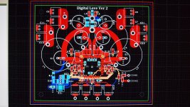
Thank you for the kind words. I have been designing LED drivers and LI ION Battery charger for my other pet projects. I currently own a 2a3 AMP and a 100w CLASS A amp. My speakers are from Omega - 3XRS, I only need a couple watts. To be honest, the board shown in the pics is designed for a couple watts. I feel my 3118 board, in the current format, will be a bit of disappointment for many....
Let me introduce you to the TAS5611A. I just finished the layout. For me, the layout and costs are almost the same (compared to my 3118 board) . The TAS5611A has separated gate supply, bridge supply and Vdd supply. The TAS5611A is the real deal. The input gain is still 20db with an 30K input impedance. The Supply voltage is 16V to 32.5V... This Chip has legs...
90mm x 75mm
Attachments
Last edited:
Finally got my 2.0 board after more than a month of waiting.
Up until now only amp I had was Yamaha RX-396 but SQ was good enough for non audiophile like me. I just wanted to downsize since Yamaha is fullsized hi-fi amp.
For power supply I wanted to use old laptop 19V PS but when I switched form iPod to PC hum stared. I guess that is because of ground loop. Another thing is when pot is at around middle there is a lot more hum than at each end. I'll have to find better pot and better PS.
Love the skull motif.
instead of a skull, it reminds me some precolumbian art...
An externally hosted image should be here but it was not working when we last tested it.
Last edited:

Can a single 12V 18a battery be used to power 2 of the pbtl mono boards?
Sure but you are limited to 15W output from each amp if you're using 4 ohm speakers.
Sure but you are limited to 15W output from each amp if you're using 4 ohm speakers.
thank you. so it will be around 3.5w for 16 ohm speaker which should be more than enough to drive 101db efficient speakers.
happy holidays everyone.
thank you. so it will be around 3.5w for 16 ohm speaker which should be more than enough to drive 101db efficient speakers.
Technically yes but usually the PBTL (mono) boards are designed for 2-4 ohm speaker impedance, not 16, which may cause problems. Even the stereo boards are typically designed for 4-8 ohm impedance but here running 16 ohm isn't that big a problem.
Technically yes but usually the PBTL (mono) boards are designed for 2-4 ohm speaker impedance, not 16, which may cause problems. Even the stereo boards are typically designed for 4-8 ohm impedance but here running 16 ohm isn't that big a problem.
Right now I have ordered the 2.0 board (blue board) to play and learn with. Can that board be modified to support 16ohm? If yes, what are the changes that need to occur. Total newbie with diy and that is the reason for the silly basic questions.
Thx
Right now I have ordered the 2.0 board (blue board) to play and learn with. Can that board be modified to support 16ohm? If yes, what are the changes that need to occur. Total newbie with diy and that is the reason for the silly basic questions.
Thx
I suspect that you have to change the output filters. There should be informations in the data sheet.
By the way, just curious, are the boards wired for mono or stereo when you received them?
Regards,
I suspect that you have to change the output filters. There should be informations in the data sheet.
By the way, just curious, are the boards wired for mono or stereo when you received them?
Regards,
I have not ordered the pbtl boards yet. For now I ordered the blue stereo boards.
Hey sorry for stupid question. What kind of wire should I use to connect speaker bindings to amp PCB? I have yuanjing 2.0 board.
If you don't modify the board, you can use the wire that you use normally to connect speakers, the only thing to consider is that the terminals on the board accept only small diameter cable, about 3mm of diameter of naked wire.
If you don't modify the board, you can use the wire that you use normally to connect speakers, the only thing to consider is that the terminals on the board accept only small diameter cable, about 3mm of diameter of naked wire.
As of right now I am using cheap thin speaker wires to directly connect speakers to terminals on board. But once I put everything in a box I will have to change this. I bought those speaker bindings that accept thicker wire or 4mm banana plug. I guess I'll have to buy some good thin wire but I have no idea what do I have to watch for or is any copper wire good enough.
As of right now I am using cheap thin speaker wires to directly connect speakers to terminals on board. But once I put everything in a box I will have to change this. I bought those speaker bindings that accept thicker wire or 4mm banana plug. I guess I'll have to buy some good thin wire but I have no idea what do I have to watch for or is any copper wire good enough.
If it is for the wiring inside the box (from the PCB terminals to your speaker binding posts), it shouldn't matter too much, the distance will be really short. Just make sure the current rating is high enough.
I know audiophiles like to use very expensive and high quality wires, but from my personal experience, i don't think it matters a lot, certainly not for short distances. But, as I said, that's a personal opinion (I don't want to argue on the internet again
)- Home
- Amplifiers
- Class D
- TPA3116D2 Amp