1. My honest congrats.
2. In the region of the wide isolation barrier, please scratch away the thin copper lines at the sides of the PCB. In the moment this copper line effectively jumpers most of the creepage distance, because it is a conductor which is very close to the primary and also very close to the secondary.
3. Take care with the creepages also in the transformer.
4. Check if the blue cap across the barrier has Y1 rating.
5. Enjoy your build! Great to see your walk of success.
Disclaimer:
My safety hints are based on my best personal knowledge, but I cannot
guarantee regarding potential errors.
Also there is no way to give full information about safety standards by a few posts. Also there is no way to notice all short comings.
It is just an attempt to reduce potential safety issues, which I noticed while zapping through the forum.
1. My honest congrats.
2. In the region of the wide isolation barrier, please scratch away the thin copper lines at the sides of the PCB. In the moment this copper line effectively jumpers most of the creepage distance, because it is a conductor which is very close to the primary and also very close to the secondary.
3. Take care with the creepages also in the transformer.
4. Check if the blue cap across the barrier has Y1 rating.
5. Enjoy your build! Great to see your walk of success.
Disclaimer:
My safety hints are based on my best personal knowledge, but I cannot
guarantee regarding potential errors.
Also there is no way to give full information about safety standards by a few posts. Also there is no way to notice all short comings.
It is just an attempt to reduce potential safety issues, which I noticed while zapping through the forum.
thanks chocoholic much appreciated GOD bless .
Hope I am not annoying you and other DIYers with my safety topics.
Safety standards are full of pitfalls.
Our company has an entire department of specialized engineers, who do nothing but checking and early consulting the design engineers on safety topics. No, I am not one of these specialized safety engineers.
..ohps just seeing now, the tape around the ferrite core should be wider.
Again the same topic - the ferrite comes close the primary and the secondary PCB.
My proposal: Make the tape much wider than the transformer (i.e. 6mm on each side) and have it 3 layers at least. I know that's looking ugly.
Keeping fingers crossed that the inside transformer construction provides sufficient isolation, cannot judge this from the distance.
Fundamental rule for you to check:
Imagine the currents wants to creep from primary to secondary along any surface.
Also indirect path which incorporate conductive parts like unconnected copper or ferrite are critical. I.e. Primary ==> core ==> secondary.
Distances along the surface of conductive material are no creepage, because the conductive material jumpers this distance.
Whereever you find a path which has less than 5-8mm creepage over isolating material, you should think how to enlarge.
Have another problem:
My Class D Board same like AUD600 but without TL072 Balanced Input stage.
Signal goes direct into TL071, have Poti 47K for Volume control before TL071 Input
If I conncet 2 Class D Board with my PC SOUNDCARD
and close POTI (no music can comes out)
then I have ground noise in speaker and cant find a way to fix it.?
If I connect 2 Class D Board with Samsung Galaxy S3 no have noise
if close POTI (no music can comes out)
It look like soundcard modulate input stage from class d board
Any idea to solve this problem ?
Have another problem:
My Class D Board same like AUD600 but without TL072 Balanced Input stage.
Signal goes direct into TL071, have Poti 47K for Volume control before TL071 Input
If I conncet 2 Class D Board with my PC SOUNDCARD
and close POTI (no music can comes out)
then I have ground noise in speaker and cant find a way to fix it.?
If I connect 2 Class D Board with Samsung Galaxy S3 no have noise
if close POTI (no music can comes out)
It look like soundcard modulate input stage from class d board
Any idea to solve this problem ?
Hi NMOS,
Connect sig GND to Main GND (star) Point
Regards
MANOJ
D
Deleted member 148505
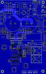
Nice all in one layout.Hi,
My new dual layer work,not completed
any suggestions pls
Regarding
MANOJ
")
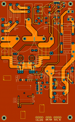
You decided to go SMD, since there's a lot of space maybe you should include totem pole buffer? and TO-247 mosfets? Gate drive should be 1/2W type. So that the DIYers can use higher current capable mosfets.
Also bridge rectifier is insufficient for high power. And the parallel relay for speaker protect is not good for class D because they will not turn on/off simultaneously. The speaker should be connected to ground when the relay is off so that when there's DC out and an arc is formed it will be redirected to ground and not to the speaker. Speaker DC protection with relays
Also put various LED indicators for easier troubleshooting.
Attachments
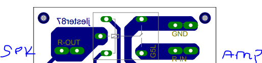
Hi Jlister,
Thank you for your good information regarding speaker protect. i will change the circuit and i feel relay paralleling not a big issue, i used a mosfet for driving relays(15Ax2 or 20Ax2).
High drive and inverter using normal IC(300mil)with base(for easy service) not a SMD one
Thank you stewin
Regards
MANOJ
Thank you for your good information regarding speaker protect. i will change the circuit and i feel relay paralleling not a big issue, i used a mosfet for driving relays(15Ax2 or 20Ax2).
High drive and inverter using normal IC(300mil)with base(for easy service) not a SMD one
nice work. decided to go smd.
Thank you stewin
Regards
MANOJ
hi all pictures of the smps
i added the primary turns so as to cool the outputs . i pushed it a bit hard without a heatsink both for the outputs ,the 7815,and the diodes rbv5006 and the mur1560 except a small heatsink to the mje350
Great work Stewin! Those pcbs look awesome, you've come a long way for sure.
Great work Stewin! Those pcbs look awesome, you've come a long way for sure.
thanks man and welcome back . a much thanks also to GOD and the diy world for the support.
hello sir manoj .. can u pls share ur aud 1000 ??
Hi Aman,
obviously i will do but it was an old carrier based design huge EMI and little noise.delta sigma design is good.
Regards
MANOJ
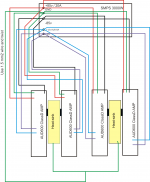
hi manoj have you ever connected 4 aud600 amps with a single power supply(same power supply e.g one +/-75 for the 4 chanels )? and did they work perfectly even though one channel was disconnected from load/speaker?
http://www.diyaudio.com/forums/clas...00-watts-using-2-mosfets-360.html#post3575203
http://www.diyaudio.com/forums/clas...00-watts-using-2-mosfets-360.html#post3575203
hi manoj have you ever connected 4 aud600 amps with a single power supply(same power supply e.g one +/-75 for the 4 chanels )? and did they work perfectly even though one channel was disconnected from load/speaker?
Hi,
AUD600 rev1.1 x 3Nos(AUD600 amp and AUD600 power) connected with DC +/- 72V /20A(AC 52v-0-52v/20A) supply rail no problem found.
Regards
MANOJ
- Home
- Amplifiers
- Class D
- My class D amp