Is there any way to add/replace the bass on the stereo tpa3118 boards? Otherwise, the sound is excellent. The wattage doesn’t seem anywhere near 30w/channel with 24v 3A power brick and efficient 4R speakers, but it’s loud enough. Just miss the bass. My Lepai LP2020TI+ amp is louder with much more bass with only the stock 12v supply.
For class D amplifiers, the output power depends on the supply voltage and the speaker impedance. A TPA3118 with 24V supply can deliver more output than a TPA2020 with 12V supply. The reason why you experience less power from the TPA3118 is most likely that the gain of the TPA3118 is less than that of the TA2020 and you accordingly have less output power though the TPA3118 could do more with more input signal.
You can always add a sub-amplifier. A sub-amplifier is nothing more than a mono amplifier with a low frequency band-pass filter at the input.
The mono amplifier can be based on a chip of the same type or a different type than the chip(s) used for the stereo amplifier.
You can always add a sub-amplifier. A sub-amplifier is nothing more than a mono amplifier with a low frequency band-pass filter at the input.
The mono amplifier can be based on a chip of the same type or a different type than the chip(s) used for the stereo amplifier.
Last edited:

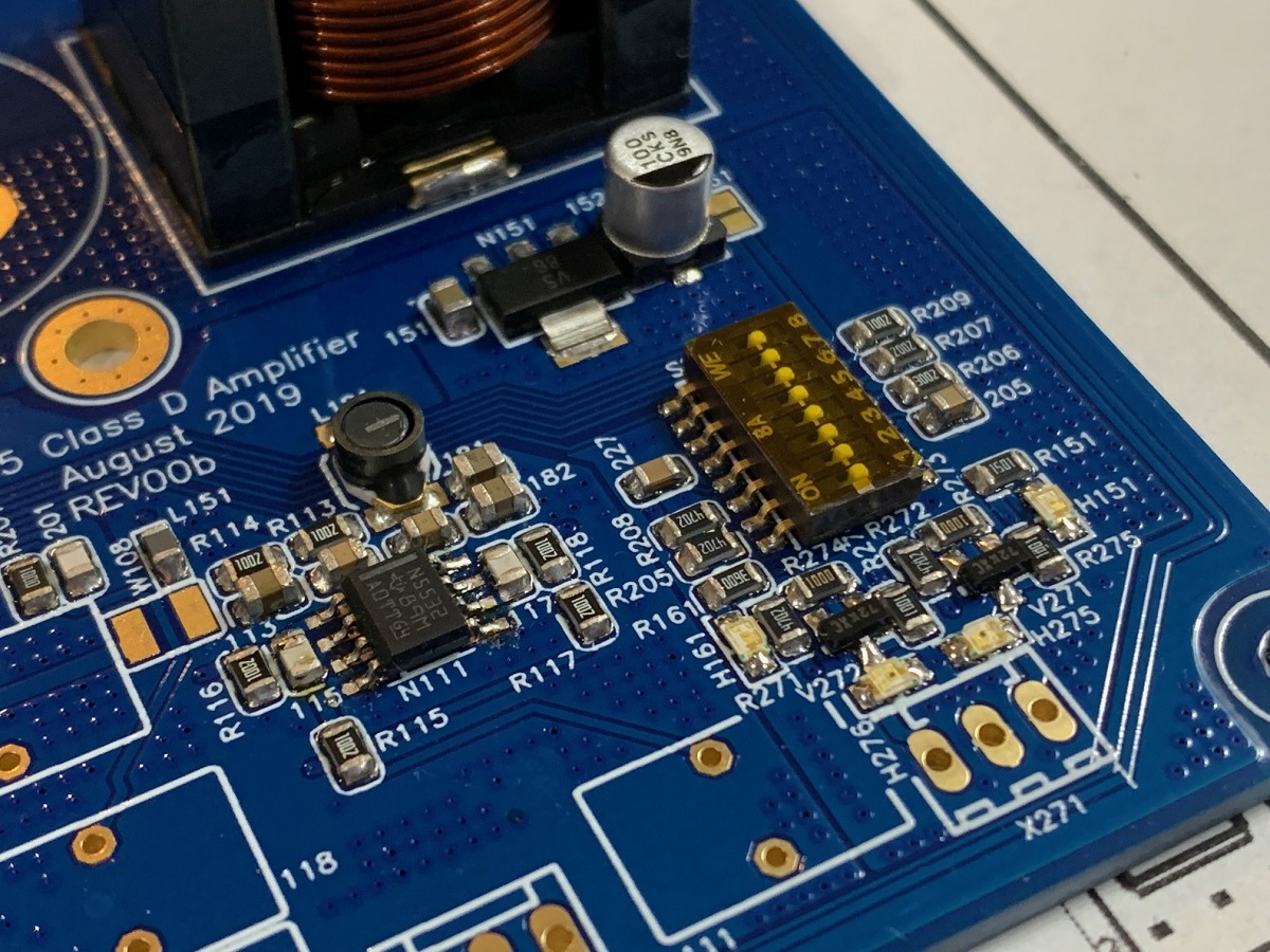
I'm using three mono TPA3118 boards to achieve 2.1 sound. Noise floor is high, causing a hiss. I see the recommendation is to remove R27 to bring the level down to 20dB, which I think will be adequate. I'm not convinced that I can remove the SMD component without damaging the board/traces/other components, so I'm wondering if I can rather put a 4k7 resistor across the inputs? If so, what would the resultant level be?
Also allied to this, I have ganged all three of the mute connections on these boards to one SPST toggle switch. It works as expected but I'm wondering if this is a smart move since I recall someone with a similar setup posting here that used three switches - ie one for each board.
Also allied to this, I have ganged all three of the mute connections on these boards to one SPST toggle switch. It works as expected but I'm wondering if this is a smart move since I recall someone with a similar setup posting here that used three switches - ie one for each board.
I have an arguably "barbaric" method for removing SMD components, but it works pretty damn well.
Step one - add some solder to each end of the (passive) component in question
Step two - grab a pair of tweezers in your non-main hand
Step three - maneuver your soldering iron in such a way that the (side of) the tip lays flat on top of the component, and the solder-wetted area of the tip reaches both blobs on the ends of the component in question
Step four - when the solder on both ends of the component is molten, grab it with the tweezers (even "through" the solder) and remove it.
Cleaning the solder off the remaining pads is optional, but welcome. You'll also wanna check that you haven't created any solder-bridges during the procedure.
I'm using three mono TPA3118 boards to achieve 2.1 sound. Noise floor is high, causing a hiss. I see the recommendation is to remove R27 to bring the level down to 20dB, which I think will be adequate. I'm not convinced that I can remove the SMD component without damaging the board/traces/other components, so I'm wondering if I can rather put a 4k7 resistor across the inputs? If so, what would the resultant level be?
Also allied to this, I have ganged all three of the mute connections on these boards to one SPST toggle switch. It works as expected but I'm wondering if this is a smart move since I recall someone with a similar setup posting here that used three switches - ie one for each board.
Hi Erik,
I am not sure if 4K7 across the input of the TPA3118 boards will work as well as the 4K7 on the output of the volume potentiometer used on the TPA3116 boards. The reason is that on the TPA3118 boards the 4K7 will be before the input signal coupling capacitors while on the TPA3116 board they were after the input coupling capacitors, as far as I remember.
Removing an SMD resistor with a soldering iron is much easier than placing an SMD resistor. I use a method similar to Krohn:
Use the fine tip on the soldering iron. Put some solder on the two terminal ends of the resistor you want to remove such that the solder form small balls. Clean the soldering iron tip. Place the soldering iron tip on one end of the resistor, in contact with the solder ball, and push toward the body of the resistor. Then, move the soldering iron tip to the opposite end of the resistor and push toward the body of the resistor from that end. Move the tip from one end to the other end of the resistor more times such that the solder on both ends melt. After a while, also the glue that held the resistor in place during wave-soldering will give in and the resistor starts moving. Most often the small SMD resistor will stick to the tip of the soldering iron due to the surface tension of the solder. That’s it!
Last edited:
Thanks to Khron and FauxFrench for this info - I'm happy with the procedure after reading this. I'm mostly concerned about collateral damage, as the tip on the smallest soldering iron I have still looks massive against the components. I've had a good look with some magnification and it looks doable, so I'll get to it this weekend.
As a matter of interest, what temperature can these SMD components typically withstand before being damaged?
As a matter of interest, what temperature can these SMD components typically withstand before being damaged?
Attachments
![IMG_1691[1].jpg](/community/data/attachments/722/722558-e6d4b2bbec0e57f6c3d6159d1b0700b7.jpg)
Thanks to Khron and FauxFrench for this info - I'm happy with the procedure after reading this. I'm mostly concerned about collateral damage, as the tip on the smallest soldering iron I have still looks massive against the components. I've had a good look with some magnification and it looks doable, so I'll get to it this weekend.
As a matter of interest, what temperature can these SMD components typically withstand before being damaged?
Do you have an old board that is faulty or something like that to practice on? I'm sure you will have some sort of electronic item knocking about that is disposable that you can take apart!
")
................ I've had a good look with some magnification and it looks doable, so I'll get to it this weekend.
As a matter of interest, what temperature can these SMD components typically withstand before being damaged?
Practicing on a defect board is a very good idea.

Your concern in this case is to get the resistor off without damage to the PCB tracks and pads. The resistor will be lost because it is so small. Most components can stand some 200 degrees Celsius but it depends on the type of component. SMD components are not intended to be reused.
I use brute force with a scalpel. The solder is soft and a few “cuts” on one side is enough to get the blade under the smd so I can pry it off.
But I also have success with a plier and crush the resistor. I figure that if I break the board i can always replace the whole thing since they are cheap.
So far so good..
But I also have success with a plier and crush the resistor. I figure that if I break the board i can always replace the whole thing since they are cheap.
So far so good..
That's not necessarily true - i've got plenty of SMD resistors and ceramic caps i've scavenged from boards, and i've reused plenty of them with no issues (so far, anyway) 
Your concern in this case is to get the resistor off without damage to the PCB tracks and pads. The resistor will be lost because it is so small. Most components can stand some 200 degrees Celsius but it depends on the type of component. SMD components are not intended to be reused.
You are absolutely right and I have also managed. I wrote that "SMD components are not intended to be reused". Apart from that component manufacturers dis-advice any reuse, SMD resistors are so small that they tend to disappear when you clean the soldering tip with the sponge.
Unless you are experienced with manual SMD-component handling, do not worry about how you can also reuse the component you remove.
But, you are right!
Unless you are experienced with manual SMD-component handling, do not worry about how you can also reuse the component you remove.
But, you are right!
Thanks guys for the advice and suggestions - I found an old Bluetooth receiver with many SMD components on it and used that for practice. Started with some capacitors that are at least twice the size of the resistors I intended removing, then moved on to smaller components. Short story is that I have now removed R27 on the TPA3118 boards, nice and clean with no damage anywhere. Gain is just where I like it to be and the boards are as quiet as the grave.
A $40 hot air SMD pencil is a great tool to have to remove stuff and also to reinstall with paste. Paste is so much neater than spool solder and iron.
CO-Z 858D LED Display SMD Soldering Rework Station https://www.amazon.com/dp/B01MR2IWBN/ref=cm_sw_r_cp_api_i_-D5MDbVG38XXW
About 20 second of low heat application and the part can be simply lifted off with tweezers.
Use copper braid and iron to clean pad off. Add a dab of paste with syringe. Place part and rebar with hot air for perfect joints.
Here is example of what you can do at home with solder paste and hot air pencil:
Last edited:
For SMD stuff I use a pair of titan tweezers. These do not conduct heat and you can hold the part while you solder. Normal steel tweezers need to be heated too, this increases the critical time you fry the parts.
Then, use a magnifying glass. I have one with an LED light build in. Even if your eyes are very good, this is much less stress and might save you from a bad headache.
Last, a calm hand. Try to find a position where your hand and arm rest on the table. This is much easier than holding the arm in the air. I had to work on watches quite a while ago, this was good practice for SMD soldering...
When you finish a board under the lens and then look at it with bare eyes, you will hardly believe you did this, as parts are so small.
If you want to do this kind of hobby more often or want to build a complete amp, get a hot air station and solder paste right away.
Only for very limited work, you might use a 12V soldering iron and a reel of finest solder.
I use such a lamp, fixed at the table:
Attachments

6 channel TPA3118 amp build
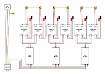
Guys.. just wanted to ask for your advice/critique/recommendations for this? I'll be using this for a 4-way speaker, using a Linux PC with PulseAudio Crossover Rack by TFive. The sub will be powered by a different class AB amp. Each 3118 module pair will be supplied with a single 19V 4.72A laptop brick. The mute for each module will be turned on/off by a single switch with 2 rows of 6 terminals (I don't know the name but I got it off an old Yamaha amp). I've tested a pair
already, but just wanted your advice before I assemble everything. This is my first build
And also, how would I add an LED power indicator after each brick?
Thanks!
Cheers,
Kieran
Attachments
Usualy power supply and amps have a power LED.
If you need an additional LED, you have to use a resistor in line with it. Value depends on the LED you use.
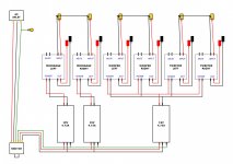
The use of a 100W supply for the tweeter is over kill.
Better give each woofer a brick and use a single one for mid and tweeter. Makes more sense, might sound better.
As far as I know the mute pin´s can all be connected to one switch, but will do no harm if you switch each one separate. Just a lot of wires.
Take care with earth wires or you will have a whole lot of noise. Set the amp modules to the lowest amplification, this will reduce noise, too!
PS let the amp modules burn in on a resistor or cheap speaker, if they fail, this is probably during the first hour of use. So you do not risk expensive speakers.
If you need an additional LED, you have to use a resistor in line with it. Value depends on the LED you use.
The use of a 100W supply for the tweeter is over kill.
Better give each woofer a brick and use a single one for mid and tweeter. Makes more sense, might sound better.
As far as I know the mute pin´s can all be connected to one switch, but will do no harm if you switch each one separate. Just a lot of wires.
Take care with earth wires or you will have a whole lot of noise. Set the amp modules to the lowest amplification, this will reduce noise, too!
PS let the amp modules burn in on a resistor or cheap speaker, if they fail, this is probably during the first hour of use. So you do not risk expensive speakers.
Last edited:
Usualy power supply and amps have a power LED.
If you need an additional LED, you have to use a resistor in line with it. Value depends on the LED you use.
The use of a 100W supply for the tweeter is over kill.
Better give each woofer a brick and use a single one for mid and tweeter. Makes more sense, might sound better.
As far as I know the mute pin´s can all be connected to one switch, but will do no harm if you switch each one separate. Just a lot of wires.
Take care with earth wires or you will have a whole lot of noise. Set the amp modules to the lowest amplification, this will reduce noise, too!
PS let the amp modules burn in on a resistor or cheap speaker, if they fail, this is probably during the first hour of use. So you do not risk expensive speakers.
Thanks for your reply!
About the LED, the modules already have a very small power on LED, I was just thinking of adding this indicator light to the front panel of the enclosure, one for each pair, so connect it to the DC side of the laptop bricks. Will try it out. The AC switch already has a light of its own around the button, the assembly of which I got from a broken yamaha amp.
For the power supply setup you mentioned, you mean like in the first pic attached? Would it be okay to connect the midrange pair and the tweeter pair to a single brick? How about if I use an additional 12V 2A for the tweeter pair only? This is the ps that I tested the boards with.
And about burning in the boards, I've tested a pair with the 12V ps on two 8" drivers for maybe several minutes. When the amp is connected to the source (phone) and turned on, there's this clicking sound coming out from the speakers, no buzz or hum, just this annoying clicking, and it stops when the music plays. I hooked up the switch for the mute, connected the boards to an old Technics 3-way, powered on the amp (but still on mute, and there was no clicking sound), played the music and unmuted the boards. It sounded really nice and clear, although the bass is somewhat lacking, or thin maybe. I played the boards straight for a couple of hours, testing on different kinds of music. I'll be getting the enclosure tomorrow so hoping to hook everything up and try out PAXOR. I'm planning to test the whole setup first, and see if I need to do some modding on the boards as previous posts suggested (changing the gain, snubbers, replacing the 330uf caps, etc).
Final question, is the grounding/earthing in the diagram okay? I'm using twisted 2 core shielded cables for the input, very short, and twisted awg18 wires for the output. Sorry for the long post, but thank you for your reply.
Cheers,
Kieran
Attachments
KieranFM,
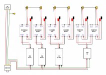
Not sure what your question is. What you have should work but you probably have too many PSU’s. Unless you were planning on running them full power. The problem with multiple amps is sometimes they have a modulation frequency interference and hence need to be in master/slave mode with frequency connection.
Clicking you have sounds like maybe one of the psu’s is cycling on/off? Or a bad PSU. What amps are you using?
I would use separate power supplies on all of them unless you plan on using frequency master/slave option. That will reduce interference. Sketch you have should work but make sure you use star topology for ground - not bus topology.
Cheers,
X
- Home
- Amplifiers
- Class D
- Cheap TPA3118D2 boards, modding them and everything that comes with it